Fig.1 fig.2 fig.3, Controls 6. preparation, Welding procedure – Sealey MW140A User Manual
Page 4
Original Language Version
5. CONTROLS
6. PREPARATION
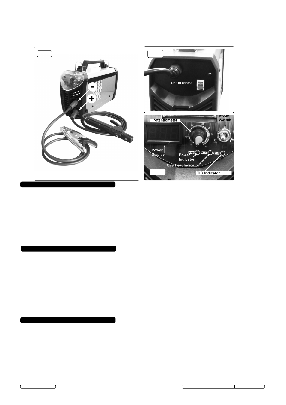
5.1. BACK PANEL (Fig.2).
Rocker switch. Turns mains power on and off.
5.2. FRONT PANEL (Fig.3).
5.2.1.
Potentiometer. Regulates welding current with graduated outer scale in amps. The amperage selected is displayed in the Power
Display.
5.2.2.
Mode Switch. For arc welding, the switch should be in the left position. For TIG welding the switch should in the right position.(leads
for use as a TIG welder are not supplied with this machine but are available as an optional extra)
5.2.3.
Power Indicator. Illuminates when machine is switched on ready for use.
5.2.4.
TIG Indicator. Illuminates when machine is switched over for TIG use (see 5.2.2.).
5.2.5.
Overheat Indicator. Illuminates when the circuitry within the machine overheats. Allowing the inverter to cool down naturally will
restore operation after a period of time. see ratings plate for details of duty cycle.
6.1. The welding current must be regulated according to the diameter of the electrode in use and the type of joint to be welded. see
diameter/current chart below.
6.2. The mechanical character of the weld will be determined not only by the current used, but also by the diameter and quality of the
electrode, the length of the arc and the speed and position of the user. The condition of the electrode is an important factor and it must
never be wet or damp.
6.3. ensure that the workpiece is correctly secured before operating the inverter.
WARNING! Ensure that you read, understand and follow the safety instructions. Place the welding mask in front of your face
before striking the arc.
7.1. ARC WELDING
7.1.1. strike the electrode tip on the workpiece as if you were striking a match.
7. WELDING PROCEDURE
fig.1
fig.2
fig.3
WARNING! Cable connectors must be turned into the quick plugs fully to ensure a good electrical contact.
Loose connections will cause overheating, rapid deterioration and loss in efficiency.
DO NOT use welding cables over 10m in length.
With the exception of a metallic workbench DO NOT connect the return cable to any metallic structure which is not part of
the workpiece, as this will jeopardise weld quality and may be dangerous.
Electrode ø (mm) ............................... Minimum Welding Current ...................... Maximum Welding Current
1.6................................................................................................. 25 ................................................................50
2.0................................................................................................. 40 ................................................................80
2.5................................................................................................. 60 .............................................................. 110
3.2................................................................................................. 80 ..............................................................160
4.0............................................................................................... 120 ..............................................................200
WARNING! DO NOT hit the electrode on the workpiece, as this may damage the electrode.
7.1.2. As soon as the arc is struck, maintain a distance from the workpiece equal to the diameter of the electrode. Keep this distance as constant
as possible for the duration of the weld. As you advance along the workpiece the angle of the electrode must be maintained at
between 20º and 30º. see fig.4.
7.1.3.
At the finish of the weld, bring the end of the electrode backward in order to fill the weld crater and then quickly lift the electrode from the
weld pool to extinguish the arc.
WARNING! Hot metal such as electrode stubs and workpieces should never be handled without gloves.
MW140A MW160A MW180A MW200A Issue No1 29/01/13
© Jack sealey limited