Fig.4, Ratings plate, Troubleshooting – Sealey MW140A User Manual
Page 5: 8 . maintenance
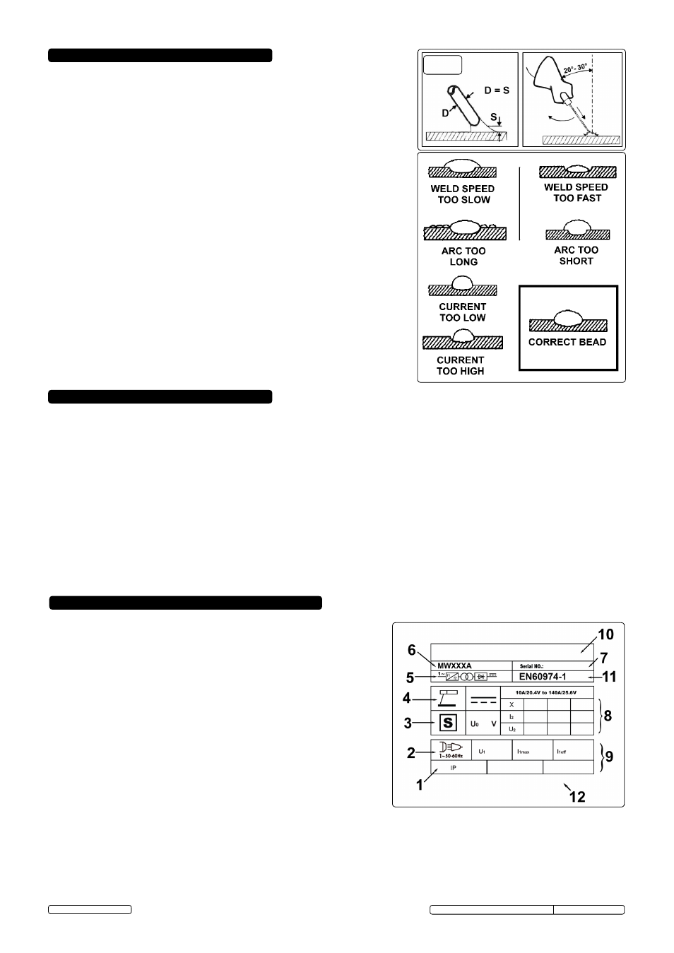
10. RATINGS PLATE
The ratings plate on the inverter gives the following data:
1 - Rating of internal protection provided by casing.
2 - symbol for power supply line: 1= single-phase AC.
3 -
S: Indicates that welding may be carried out in environments with a
heightened risk of electric shock e.g. very close to large metallic objects.
4 - Welding procedure: manual arc welding with covered electrode
5 - symbol for internal structure of the welding machine.
6 - Model No.
7 - Manufacturers serial Number for welding machine identification.
8 - output.
Uº: Maximum no load voltage.
I², U²: Current and corresponding normalised voltage that the
welding machine can supply during welding.
X: Welding ratio based on a 10 minute duty cycle. 30% indicates 3
minutes welding and 7 minutes rest, 100% indicates continuous welding.
A/V-A/V: shows the range of adjustment for the welding current
(minimum - maximum) at the corresponding arc voltage.
9 - Power supply
U
1
: Alternating voltage and power supply frequency of welding machine.
(allowed limit ± 10%)
I
1
max
: Maximum current absorbed by the line.
I
1
eff
: effective current supplied.
10- Manufacturer's details.
11 -The eURoPeAN standard relating to the safety and construction
of arc welding machines.
12- safety regulation symbols shown here.
9. TROUBLESHOOTING
If you have a problem with the inverter, check to ensure that the following are correct:
● Check that the welding current, which is controlled by the potentiometer (fig.3), is suitable for the diameter and type of electrode being
used.
● When the mains switch is on, check that the power lamp is on. If this is not the case then there may be a mains supply problem.
● Check the overheat indicator - has the thermal cut-out activated? This indicates either an over or under voltage or short circuit. If the
thermal interrupter has activated, wait for the machine to cool down before restarting.
● ensure that you are using the correct supply voltage.
● Check the machine output and ensure there is nothing causing a short-circuit.
● Check that all circuit connections are correct. In particular check that the work clamp is correctly attached to the workpiece. ensure that
there is no grease, paint etc. on the surface.
8 . MAINTENANCE
WARNING! BEFORE CARRYING OUT ROUTINE MAINTENANCE, SWITCH
OFF THE WELDING MACHINE AND DISCONNECT IT FROM THE MAINS
POWER SUPPLY.
WARNING! IF THE WELDING MACHINE IS NOT FUNCTIONING PROPERLY
REPAIRS SHOULD BE CARRIED OUT ONLY AND EXCLUSIVELY BY
AUTHORISED SERVICE ENGINEERS.
WARNING! BEFORE REMOVING THE WELDING MACHINE PANELS,
SWITCH OFF THE MACHINE AND DISCONNECT IT FROM THE MAINS
POWER SUPPLY. Wait 10-15 seconds after the unit is switched off for the
capacitor to discharge.
8.1. Periodically remove the casing and, with a low pressure air flow (max 1bar
or15psi),remove dust from inside the machine.
8.2. do not direct compressed air onto the electronic circuit boards, these should be
cleaned with a very soft brush.
8.3. ensure that all electrical connections are tight and check the wiring for damage
to the insulation.
8.4. ensure that the casing is correctly replaced and secured before attempting to
use the inverter.
8.5. Keep the outside of the machine clean by wiping with a soft, dry cloth.
For any other service or maintenance, contact your local Sealey service
agent.
Original Language Version
fig.4
MW140A MW160A MW180A MW200A Issue No1 29/01/13
© Jack sealey limited