Fig.1 fig.2, Fig.4 fig.3 – Sealey PP40H User Manual
Page 4
DO NOT make the earth connection to the part of the workpiece that will be removed.
4.5.
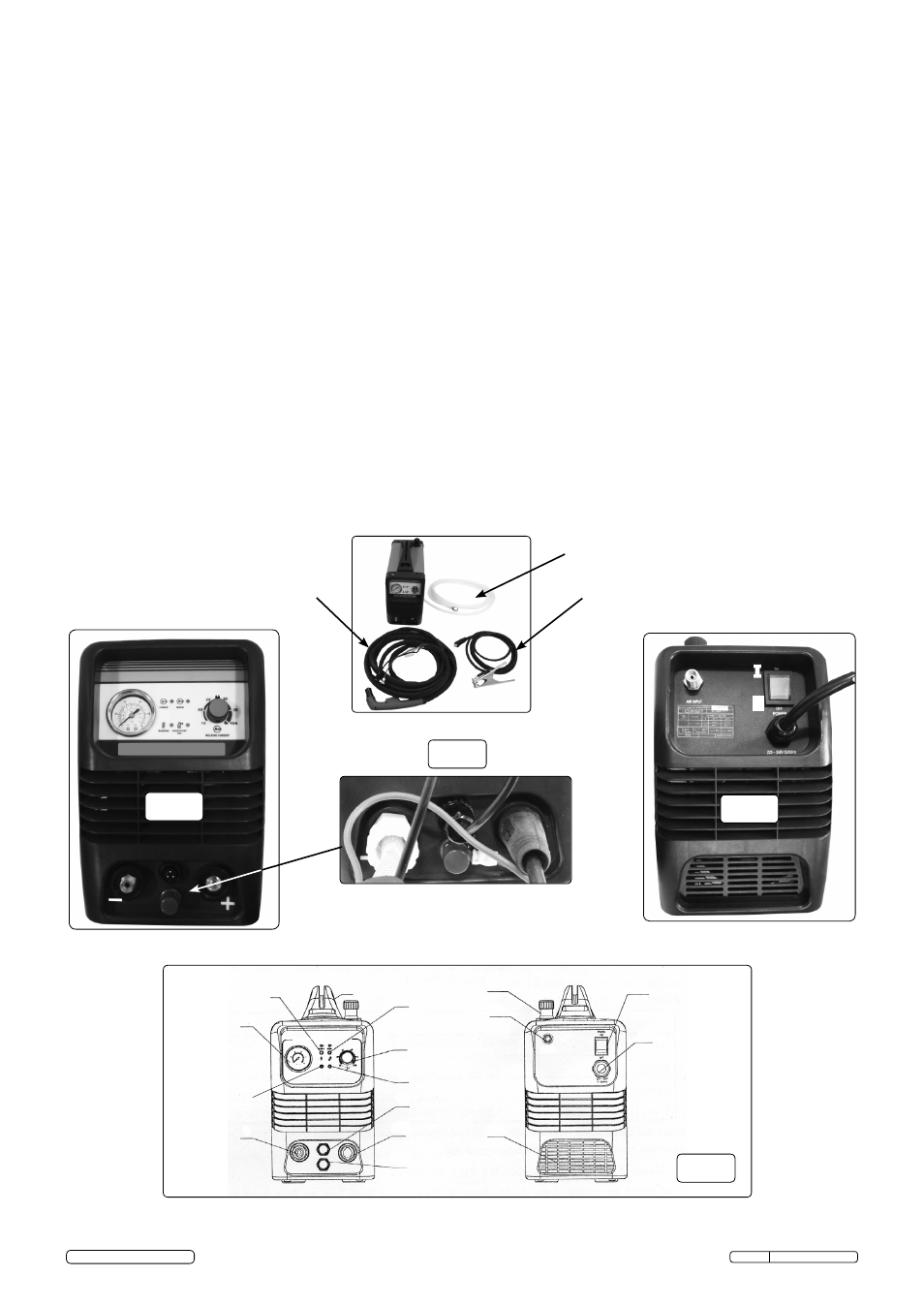
Isolation switch (see safety instructions for supply connection)
The I/O (on/off) switch is located at the rear of the machine (fig.2) and the switch will illuminate when switched on. A green LED will
also illuminate on the front panel (fig.1) indicating that mains power is present and the machine is in the ‘ready’ condition. The
control and duty circuits are now live but the torch will remain in ‘stand-by’ mode until the air supply is connected and the torch
button is pressed.
4.6.
Cutting regulator
The cutting current is regulated by the knob/potentiometer on the front panel (fig.1).
4.7.
Torch control
When the machine is turned on, the green indicator light (fig.1) will show that the torch is in “Stand-By” mode.
4.7.1.
When the torch button is pressed the machine is activated and a red LED will illuminate (fig.1) indicating the presence of the pilot
arc. As a safety feature, should the following situations arise, the torch will automatically de-activate:
a) During Post-Air (>30sec) phase.
b) If the pilot arc is not moved to the workpiece within 2 seconds.
c) If the cutting arc is interrupted because the torch is held too far from the workpiece, or if the electrode is worn out, or if the torch
has been forced away from the workpiece.
d) If the warning LED illuminates indicating either mains voltage fluctuation or overheating.
4.8.
Thermal switch and mains voltage fault
If the yellow LED (fig.1) on the front panel illuminates this indicates a mains voltage or thermal problem and the machine will be
automatically shut down as a result of one of the following:
a) The power transformer has overheated.
b) There has been a decrease or increase in the mains voltage supplied to the machine.
When the safety switch is activated in this way the problem is normally self-rectifying, and dependant upon duty cycle time, see
rating plate in section 9. The switch will re-set and the LED will go out and the machine is then ready for use again.
4.9. Torch
Although the machine and torch may be fully powered, the torch button is the only way to activate the cutting process.
4.9.1.
To turn the cutting process on, the torch button must be fully depressed.
4.9.2.
Release the button and the cutting cycle will stop immediately. The cooling air (post-air) will continue to flow for a further 30
seconds.
Note: To minimise the possibility of accidental starting, the button must be pressed for at least 1/5 of a second before the cutting
operation will start.
fig.1
fig.2
Original Language Version
PP40H Issue: 1 - 08/05/13
"+"
ve
to
workpiece
Torch
connections and
"-"
ve
I
0
I/O Switch
Power cable
Regulator
Air supply
Fan cover
Torch red LED
Warning
temperature
amber LED
Low air pressure
amber LED
Current adjust
Pressure gauge
Power on
green LED
Air line
connection
to torch
3 pin connection
Pilot arc
connection
Work piece
connection
fig.4
fig.3
Parts identification for Fig.1 and Fig.2
Handle
Pneumatic hose
"+"
ve
lead
Torch pneumatic
hose, pilot arc
connection and
3 pin plug lead
© Jack Sealey Limited 2013