Fig.7 fig.8, Fig.6, Fig.5 – Sealey PP40H User Manual
Page 5
WARNING! Before operating the machine ensure that you read, understand and apply Section 2 safety instructions and that you
have familiarised yourself with the controls. Ensure that the machine is disconnected from the power supply before moving or
changing accessories.
6.1. Set-up
(air supply connected in section 5)
6.1.1.
Check that the earth cable is correctly clamped to the workpiece or work bench (fig.5).
6.1.2.
Switch on the mains power supply. Switch on the machine by operating the I/O switch on the rear panel (fig.2).
6.1.3.
Set the current regulation control (fig.1) to the required value.
6.1.4.
Press the torch button and release to commence the flow of cooling air (post-air).
6.1.5.
Allow the air flow to continue to remove any condensation from the torch. The air flow will
automatically stop after approx. 30secs.
NOTE: Longer than standard nozzles and electrodes are available to improve accessibility in
awkward cutting positions. Ask your Sealey dealer for details.
6.2.
Cutting from the edge
6.2.1.
Bring the torch nozzle toward the edge of the workpiece and hold it at 3mm above the cutting line.
6.2.2.
Press and hold down the torch button. After about 1/5 of a second of pre-air, the pilot arc will be
generated. If the distance between the torch nozzle and the workpiece is correct, the arc will
immediately jump to the workpiece and the cutting process will begin.
6.2.3.
Move the torch slowly and smoothly forward, on the surface of the workpiece, along the cutting line.
6.2.4.
Adjust the cutting speed according to the thickness of the material and the selected current.
6.2.5.
Check the underside of the cut. The arc should make a 5 - 10° angle with the vertical in the
opposite direction to the cutting direction (fig.7).
6.3.
Cutting from the centre
6.3.1.
Place the torch nozzle at an angle to the surface at the start-of-cut position (fig.8).
5.3.2.
Initiate the pilot arc, then slowly and smoothly bring the torch head to the upright position.
The arc will pierce the workpiece and cutting can start.
6.4.
Arc off
6.4.1.
Release the torch button to switch off the arc. The post-air will continue to flow, cooling the nozzle.
6.4.2.
Other reasons for the arc ceasing are:
a) The distance between the torch nozzle and workpiece is too great.
b) You have completed a cut and have continued beyond the edge of a workpiece.
c) The waste falls away from the workpiece thus increasing the gap.
fig.7
fig.8
230V-1ph
Work piece
"+"
ve
cable
Torch
Air line
"-"
ve
3 pin connection
6. OPERATION
Original Language Version
PP40H Issue: 1 - 08/05/13
© Jack Sealey Limited 2013
5.1.
Connect the air supply to the inverter. Pull up the regulator knob, sited on the inverter top face to regulate and push down to lock.
5.2.
Ensure that the air supply pressure is set to a minimum of 80psi. The PP40H inverter requires 45-70psi and can be adjusted locally
by rotating the regulator knob in (5.1). The inverter pressure gauge is on the front face in (fig.1).
p
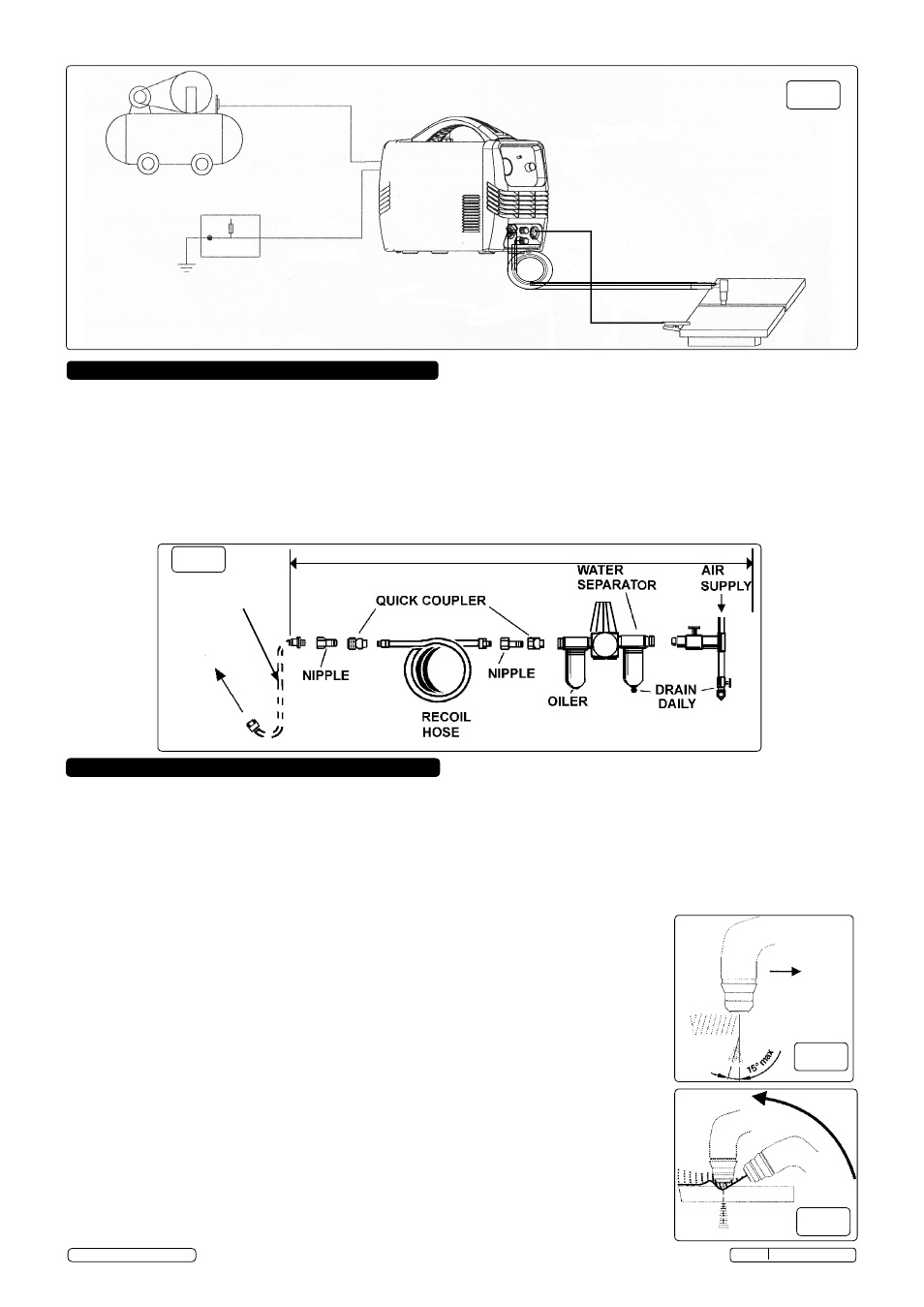
WARNING! Ensure that the air supply is clean and lubricated by fitting an filter, regulator and lubricator in the supply air line.
5.3.
Drain the compressor air tank daily.
5.4.
Clean the compressor air inlet filter screen weekly.
5.5.
Line pressure should be increased to compensate for unusually long air hoses (over 8 metres). The minimum hose bore should be
10mm and fittings must have the same inside dimensions.
5.6.
Keep hoses away from heat, oil and sharp edges. Check hoses for wear, and make certain that all connections are secure.
5.
AIR SUPPLY
fig.6
TO INVERTER
Customer supplied air line equipment
HOSE SUPPLIED
WITH INVERTER
fig.5