Introduction & specification, Assembly 4. preparation – Sealey MIGHTYMIG150 User Manual
Page 3
2. INTRODUCTION & SPECIFICATION
IMPORTANT: These insTrUcTiOns cOnTain The infOrmaTiOn yOU reqUire TO prepare yOUr machine fOr weLding, TOgeTher wiTh a
mainTenance and a TrOUbLeshOOTing secTiOn.
ThE INsTRUCTIONs ARE NOT INTENDED TO TEACh YOU hOW TO WELD. if yOU haVe nO
experience, we recOmmend ThaT yOU seek Training frOm an experT sOUrce. mig weLding is reLaTiVeLy easy, bUT dOes reqUire a
sTeady hand and sUperVised pracTice On scrap meTaL, as iT is OnLy wiTh cOnTinUed pracTice ThaT yOU wiLL achieVe The desired
resULTs.
INTRODUCTION: Our professional range of MIGHTYMIG welders all feature a heavy-duty high output transformer and forced air cooling to maximise duty cycle
performance. MIGHTYMIG150 is supplied with a comfort grip non-live torch, 1.8mtr earth cable, 1mtr gas hose, 0.45kg flux cored wire and 1.0mm contact tip. This
unit is supplied set up in the gasless mode but can be switched easily to use with gas by a simple change of polarity, and the purchase of a gas conversion kit.
3. ASSEMBLY
4. PREPARATION
Model No. . . . . . . . . . . . . . . . . . . . . . . Mightymig150
Welding Current . . . . . . . . . . . . . . . . . . . . . . . . . . 150A
Wire Capacity . . . . . . . . . . . . . . . . . . . . . . . . . . . 0.9kg
Duty Cycle . . . . . . . . . . . . 100% @ 30A, 15% @ 105A
Cooling System . . . . . . . . . . . . . . . . . . . . . . Forced Air
Gas Type . . . . . . . . . . .CO²/Argon mix & Argon & CO²
Torch . . . . . . . . . . . . . . . . . . . . . . . . . . . . . . . .Non-live
Power Input . . . . . . . . . . . . . . . . . . . . . . . . . 230V 1ph
Absorbed power. . . . . . . . . . . . . . . . . . . . . . . . . 4.5kW
Case size . . . . . . . . . . . . . . . . . . . . . . . . . . . . . Medium
Weight . . . . . . . . . . . . . . . . . . . . . . . . . . . . . . . . . 26kg
Flux cored wire (0.9kg x Ø0.9mm) . . . . . . . . TG100/1
Replacement tips (pack of 5). . . . . . . . . . . . . TG100/3
Gas conversion kit . . . . . . . . . . . . . . . . . . .120.802032
1.3
GAS SAFETY
Store gas cylinders in a vertical position only and ensure the storage area is correctly secured.
DO NOT store gas cylinders in areas where the temperature may exceed 50°C. DO NOT use direct heat on a cylinder. Always keep gas cylinders cool.
DO NOT attempt to repair or modify any part of a gas cylinder or valve and DO NOT puncture or damage a cylinder.
DO NOT obscure or remove any official labels on a cylinder. Always check the gas identity before use. Avoid getting gas cylinders oily or greasy.
DO NOT lift a cylinder by the cap, guard or valve. Always keep caps and guards in place and close valve when not in use.
fig.3
fig.4
3.1
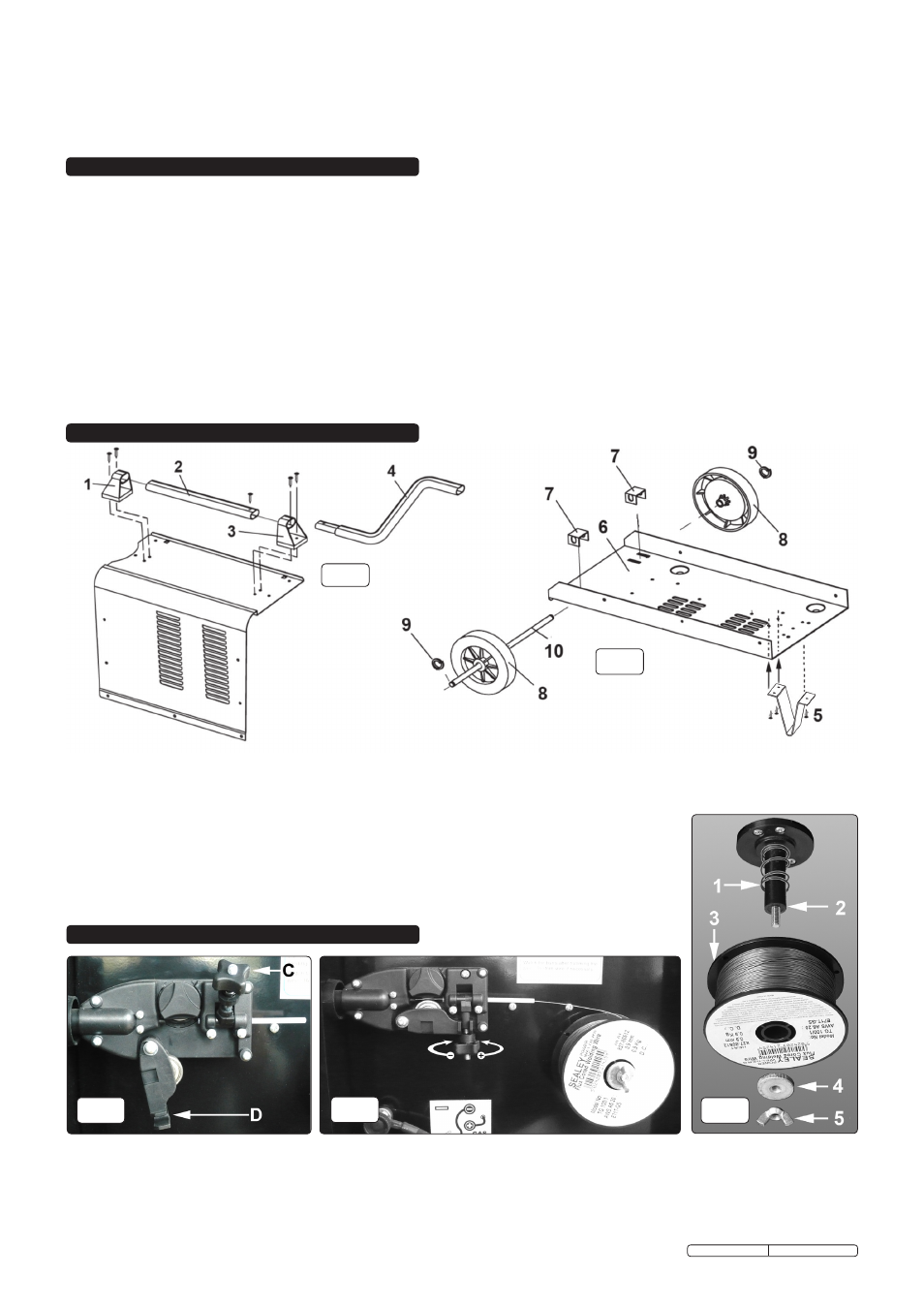
Assembly of wheels: (See fig.2)
3.1.1 Drop the axle brackets (7) through the slots in the rear of the bottom tray (6).
3.1.2 Attach a circlip (9) to one end of the axle (10) and slide a wheel (8) onto the axle and right up to the circlip.
3.1.3 Pass the axle (10) under the tray (6) and through the two protruding brackets (7) until the first assembled wheel is up against the side of the tray.
3.1.4 Slide the other wheel (8) onto the other end of the axle (10) and secure it by attaching a circlip (9) to the end of the axle.
3.2. Assembly of front foot: (See fig.2)
3.2.1 Place the foot (5) onto the underside of the tray (6) ensuring that the three holes on the foot align with the holes in the
tray. Fix the foot in place with three self tapping screws.
3.3
Assembly of handle: (See fig.1)
3.3.1 Attach the rear handle bracket (1) to the top of the casing using two self tapping screws. Slide the straight handle (2) into
the bracket (1) and slide the other bracket (3) onto the front end of the handle. Secure bracket (3) with two self tapping
screws. Insert the handle extension (4) into the front end of the handle and secure it with a self tapping screw.
fig.1
fig.2
fig.5
4.1
Fitting a reel of wire:
4.1.1 Lift the black catch on the side of the welder and open the side compartment to gain access to the wire feed unit mechanism and the wire spool holder.
See fig.3. The welder is supplied with a mini spool containing 0.45kg of flux cored wire.
4.1.2 Referring to fig.5, rotate the butterfly nut (5) anti-clockwise and remove it from the threaded spindle together with the pressure disc (4). Leave the spring (1)
on the spindle (2).
4.1.3 Place the wire reel (3) over the spindle and down onto the spring ensuring that the wire will withdraw from the top of the spool in a forwards direction
towards the wire feed unit.
Original Language Version
MIGHTYMIG150 Issue: 2 - 26/02/10