Maintenance, Ratings plate – Sealey MIGHTYMIG150 User Manual
Page 5
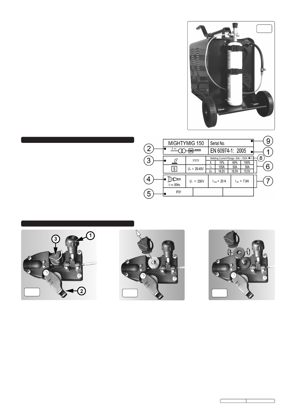
fig.10
7.6.1 Turn the gas regulator knob halfway for a 2ltr/min flow and all the way for maximum flow of 4ltr/min.
7.6.2 Always remove the flow regulator after use if the machine is to be stored for any length of time.
7.7
Gas types. Welding mild steel with CO² gas is appropriate for most welding tasks where spatter
and high build up of weld do not pose a problem. To achieve a spatter-free and flat weld however,
you must use an CO²/Argon mixture. To weld aluminium use:
Argon gas 0.8mm Contact Tip 0.8mm Aluminium Wire (MIG/2/KAL08)
7.8
Cylinder sizes. The platform at the rear of the welder will support cylinders up to a diameter of
140mm, a height of 500mm and a maximum weight of 10kg. If you wish to use larger cylinders
they must be properly secured to a separate welding trolley. An industrial gas cylinder adaptor kit
will be required. Contact your local Sealey dealer to order these items.
7.8.1 The following table is an estimated duration of cylinders based on a flow rate of 2 litres per
minute. Actual duration will be dependant upon various job conditions including the operator’s welding
technique. All times are therefore approximate.
Disposable cylinders: CO²/100 390g = 1-1/4hours.
CO²/101 600g = 2 hours.
Argon ARG/100 300g = 1hour.
Argon/CO² MIX/100 300g = 1 hour.
Note: When comparing prices, always check fill weights.
7.9
Mig/Mag gas welding principles: Welding wire is automatically fed through an insulated liner to
the tip of the torch. The torch consists of a switch, liner, gas hose, and control cable. The switch
activates the wire feed roller and the gas flow. Releasing the switch stops the wire feed and gas
flow. The weld current is transferred to the electrode (the wire) from the contact tip at the torch
end. The current switches (see section 5.3) control the current to the electrode. Wire speed must
be adjusted according to current output. The higher the current the faster the wire speed. A gas
cup fits over the contact tip to direct gas flow towards the weld, ensuring that the arc welding
process is shielded from oxidisation. The shielding gas also assists heating of the weld. The torch
is connected to the positive side of a DC rectifier, and the negative clamp is attached to the workpiece.
9. MAINTENANCE
On the front of the welder is the ratings plate, giving the
following data:
1 - The standard relating to the safety and construction
of arc welding and associated equipment.
2 - Single phase transformer - rectifier.
3 - Welding with a continuous flow of welding wire.
4 - Single-phase AC supply.
5 - Rating of internal protection provided by casing.
6 - Output
U0: Rated maximum and minimum no load voltage.
I2, U2: Current and corresponding voltage.
X: Welding ratio based on a 10 minute cycle. 20% indicates
2 minutes welding and 8 minutes rest, 100% indicates
continuous welding.
8 - Welding current range.
7 - Mains Supply U1: Rated supply voltage and frequency. Imax: Maximum current.
I1eff: Maximum effective current.
9 - Serial Number. Specifically identifies each welder.
8. RATINGS PLATE
DANGER! Unplug the welder from the mains power supply before performing maintenance or service.
9.1 Wire feed unit:
9.1.1 Check the wire feed unit at regular intervals. The feed roller wire guide plays an important part in obtaining consistent results. Poor wire feed affects the
weld. Clean the rollers weekly, especially the feed roller groove, removing all dust deposits.
9.2 Torch:
9.2.1 Protect the torch cable assembly from mechanical wear. Clean the liner from the machine forwards by using compressed air. If the liner is blocked it must
be replaced.
9.3
Turning feed roller IMPORTANT: Turn the feed roller to suit the wire size.
9.3.1 There are two grooves on the feed roller, 0.6mm and 0.8mm. Always have the groove that is being used on the outside of the roller (nearest to you). To
turn the feed roller first loosen the wire tension knob and move it into its up position (see fig.11-1) then move the tensioning roller assembly to its down
position (see fig.11-2). Take hold of the triangular knob on the roller retainer and rotate it 90°anticlockwise to release it as shown in fig.11-3. Now pull the
roller retainer off the drive spindle to reveal the roller as shown in fig.12. Pull the roller off the drive spindle, flip it over and put it back on the drive spindle.
(See fig.13) The groove size you require should now be visible printed on the face of the roller. Push the roller retainer back onto the drive spindle with the
opening facing right. Ensure that the flanges at the base of the retainer, seat fully into the circular recess in the main moulding and then rotate the retainer
through 90° to lock it in place.
9.4
Contact tip (to remove tip follow steps in 4.1.8):
9.4.1 The contact tip is a consumable item and must be replaced when the bore becomes enlarged or oval. The contact tip MUsT be kept free from spatter to
ensure an unimpeded flow of gas.
9.5
Gas cup (to remove cup follow steps in 4.1.8):
9.5.1
The gas cup must also be kept clean and free from spatter. Build-up of spatter inside the gas cup can cause a short circuit at the contact tip which will
result in expensive machine repairs. To keep the contact tip free from spatter, we recommend the use of anti-spatter spray (MIG/722307) available from
your Sealey dealer.
fig.11
fig.12
fig.13
Original Language Version
MIGHTYMIG150 Issue: 2 - 26/02/10