Assembly & preparation, Fig.4 fig.1 fig.2, Fig.6 fig.5 fig.3 – Sealey SUPERMIG150 User Manual
Page 3
INTRODUCTION: All our Supermig models are suitable for welding with CO²,
Argon or CO²/Argon mix. Each uses a forced air cooling system to slow
transformer heating in oder to increase duty cycle and a non-live torch to
prevent the risk of accidentally striking an arc. All models are supplied with
an industrial Argon/CO² regulator. Welders are illustrated with gas bottles to
give an indication of size only; gas is not included. A contract for the supply of
gas should be arranged with your local gas distributor.
MODEL NO:. . . . . . . . . . . . . . . . . . . . . . . . . . . . . . . . . . . . . . . . SUPERMIG150
Welding Current . . . . . . . . . . . . . . . . . . . . . . . . . . . . . . . . . . . . . . . . . . 30 - 150A
Wire Capacity . . . . . . . . . . . . . . . . . . . . . . . . . . . . . . . . . . . . . . . . . . 0.7 - 5.0kg
Duty Cycle . . . . . . . . . . . . . . . . . . . . .100% @ 47A, 60% @ 60A, 20% @ 105A
Cooling System . . . . . . . . . . . . . . . . . . . . . . . . . . . . . . . . . . . . . . . . . .Forced Air
Gas Type . . . . . . . . . . . . . . . . . . . . . . . . . . . . . . . . . CO², Argon, CO²/Argon mix
Torch . . . . . . . . . . . . . . . . . . . . . . . . . . . . . . . . . . . . . . . . . . . . . . . . . . . Non-live
Power Input . . . . . . . . . . . . . . . . . . . . . . . . . . . . . . . . . . . . . . . . . . . . . 230V 1ph
Absorbed power. . . . . . . . . . . . . . . . . . . . . . . . . . . . . . . . . . . . . . . . . . . . . 4.1kW
Weight . . . . . . . . . . . . . . . . . . . . . . . . . . . . . . . . . . . . . . . . . . . . . . . . . . . . . 30kg
3. ASSEMBLY & PREPARATION
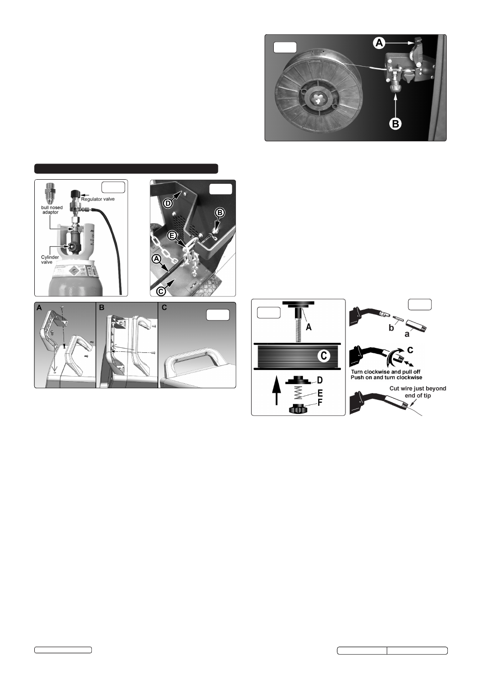
3.4.2. Referring to fig.5, rotate the pressure knob (F) anti-clockwise and
remove it from the threaded spindle together with the spring (E) and
the top disc (D). Small reels of wire will run on the spindle itself. The
larger 5kg wire reel will run on the larger diameter flange at the base of
the reel spindle (A). Place the wire reel (C) onto the spindle ensuring
that the wire withdraws from the spool in a forwards direction and on
the same side of the compartment as the wire feed unit. Place the
plastic top disc (D) over the end of the spindle followed by the reel
spring (E). Thread the pressure knob (F) onto the end of the spindle
and screw it down clockwise until the spring is partially compressed.
The reel take off pressure should be set to provide a mild braking
effect to prevent overrun where loose coils of wire form on the reel. Do
not overtighten this knob as too much braking will conflict with the wire
tension set on the wire drive unit.
3.4.3. Referring to fig.4 turn the knob on the wire lock screw (B) anti-clock
wise and unlatch it from the pressure roller moulding. Swing the
pressure roller moulding (A) away from the drive roller.
3.4.4. Straighten 40-50mm of spool wire (do not allow wire to uncoil), and
gently push wire through the plastic guide and through the 6 or 8mm
feed roller groove and into the torch liner. Refer to section 6.5
on how to reverse the roller for either 6 or 8mm wire.
3.1. Assembly.
3.1.1. Assemble the wheels as follows. Slide the rear axle through the loops
on the underside of the rear tray. Slide a wheel onto each end of the
axle and retain with the washers and split pins provided. Attach the
front foot to the underside of the welder using the screws provided.
3.1.2.
Take the front half of the handle moulding and align the two mounting
holes in it with the fixing holes in the top surface of the welder front
moulding (see fig.3A). Secure the handle with the two bolts provided (see
fig.3B). Place the rear part of the handle moulding into the back of the
front half and snap it into place. Insert the two self tapping screws
provided into the holes in the back of the handle and drive them fully
home but do not overtighten them (see fig.3C).
3.2. Connecting the gas cylinder (See Section 4.3 regarding gas types)
3.2.1. Place the lower end of the gas cylinder on to the rear tray, between the
two wheels. See fig.2-C. Allow the upper part of the cylinder to rest into
the metal support. See fig.2-D. Secure the cylinder by hooking either
end of the chain E through the metal support as shown in fig.2.
3.3. Connecting the gas cylinder
3.3.1. When using Argon or Argon mixtures, you will need to use the “bull
nose adaptor”. Fit the bull nose adaptor to the cylinder with a spanner.
(If you intend to use CO² gas the regulator will fit directly onto the
cylinder).
3.3.2. Fit the gas regulator on to the bull nose adaptor as shown in fig.1.
3.3.3. Push the black gas tube provided (see fig.2-A) onto the gas inlet
nozzle and retain it with the wire clip provided as shown in fig.2-B.
Push the other end of the tube onto the gas outlet nozzle on the
regulator and retain it with the other wire clip provided. See fig.1.
3.3.4. When you are ready to weld set the regulator flow rate to 5-8 litres/min
depending on the material to be welded, and whether there are
draughts which are strong enough to disturb the gas flow.
3.4. Fitting a reel of wire.
3.4.1. Open the side compartment on the welder by placing your finger into
the black catch and lifting both the catch and the door. The welder is
supplied with a mini spool of mild steel wire, but will accept spools of
up to 5kg without modification.
fig.4
fig.1
fig.2
3.4.5. Refering to fig.7, move the pressure roller moulding (A) back round onto
the grooved drive wheel and swing the wire lock screw (B) up to lock it
in place. See 3.5.2 regarding wire tension.
3.5. Feeding the wire through to the torch. (See fig.6)
Remove gas cup (a) and contact tip (b) from end of torch as follows:
a) Take torch in left hand with the torch tip facing to the right.
b) Grasp gas cup firmly in your right hand.
c) Turn gas cup clockwise only and pull cup out to the right.
WARNING! do not turn gas cup anti-clockwise, as this will damage
internal spring.
d) Unscrew the copper contact tip (right hand thread) to remove.
3.5.1. Check welder is switched off “0” and that the earth clamp is away from
the torch tip. Connect the welder to the mains power supply and set the
voltage switches to MIN/1.
3.5.2. Set the wire speed knob to position 5 or 6. Keeping the torch cable as
straight as possible and press the torch switch. The wire will feed
through the torch.
3.5.3. When wire has fed through, switch welder off, unplug from mains.
a) Take torch in left hand and screw contact tip back into place.
b) Grasp gas cup in right hand, push onto torch head and turn clockwise only.
WARNING! do not turn gas cup anti-clockwise, as this will damage
internal spring.
c) Cut wire so that it is just protruding from the cup.
3.6. Setting wire tension.
IMPORTANT: You must set the correct tension, too little or too much
tension will cause problematic wire feed and result in a poor weld.
3.6.1. For mild steel 0.6mm wire the wire tension screw must be fully tightened
and undone approximately two complete turns (fig.7).
3.6.2. Correct tension between the rollers is checked by slowing down the wire
between the fingers. If the pressure roller skids the tension is correct.
Try to use the lowest tension possible as too high a tension will deform
the wire and may result in blowing a fuse on the printed circuit board.
When you have completed welding disconnect the unit from the mains
supply and store it in a safe, dry place. Note: Damaged torches and
cables are not covered under warranty.
fig.6
fig.5
fig.3
SUPERMIG150.V3 Issue No:2(SP) 09/01/14
Original Language Version
© Jack Sealey Limited