Fig.14 fig.13 – Sealey SUPERMIG150 User Manual
Page 5
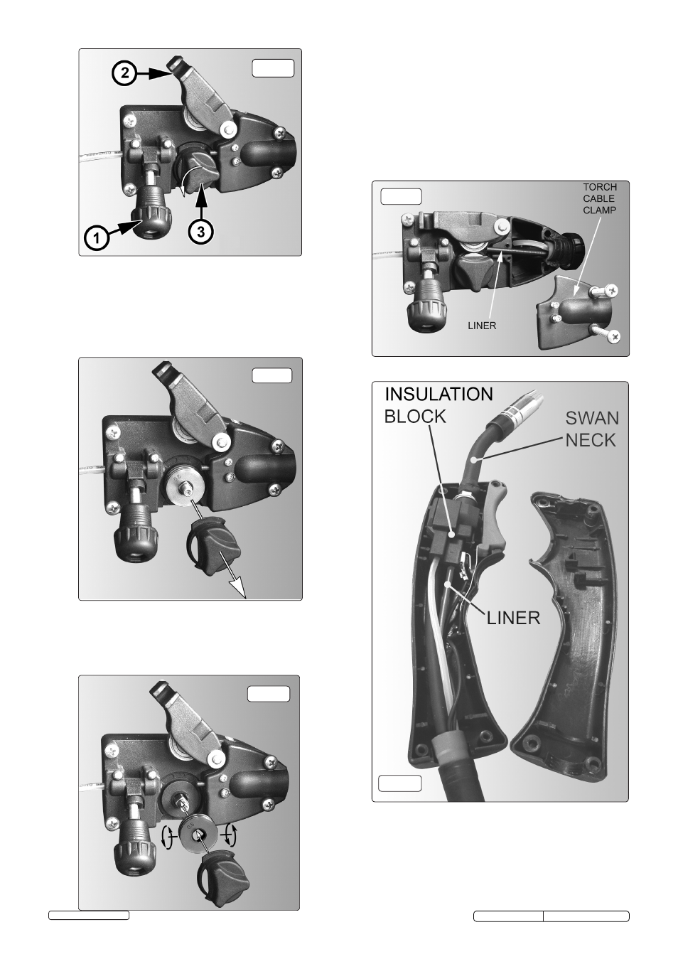
fig.12
fig.11
fig.10
6.6. Replacing wire liner.
6.6.1. A worn or damaged wire liner will seriously affect the performance of
the welder and should be immediately replaced. First wind the wire
back onto the spool and secure it. Remove the four screws securing
the torch cable clamp to the wire feed unit (fig.13) and take off the
clamp. Undo the torch case (fig.14) and pull the wire liner from the
insulation block. Pull out the liner from the torch cable and insert the
new one. Reverse the process to re-assemble. Ensure the liner is fully
inserted into the torch insulation block and reassemble the torch. Trim
the other end of the liner as close to the feed roller as possible.
Replace the torch cable clamp.
6.7. Replacing gears.
6.7.1. An inexperienced welder can allow spatter to build up in the tip and
shroud. In severe cases this can block the wire feed causing gear
damage in the wire drive. To check if the gears are worn depress the
button on the torch with the set switched on. If the gears are worn, a
grating sound will be heard coming from the wire feed motor and you
may also observe the feed roller vibrating instead of rotating smoothly.
In this is the case, return the welder to your local Sealey dealer for
repair.
6.5
Turning feed roller IMPORTANT: Turn the feed roller to suit the wire size.
6.5.1. There are two grooves on the feed roller, 0.6mm and 0.8mm. Always
have the groove that is being used on the outside of the roller (nearest
to you). To turn the feed roller first loosen the wire tension knob and
move it into its down position (see fig.10-1) then move the tensioning
roller assembly to its up position (see fig.10-2). Take hold of the
triangular knob on the roller retainer and rotate it 90°anticlockwise to
release it as shown in fig.10.3. Now pull the roller retainer off the drive
spindle to reveal the roller as shown in fig.11.
6.5.2. Pull the roller off the drive spindle, flip it over and put it back on the
drive spindle. (See fig 12) The groove size you require should now be
visible on the face of the roller. Push the roller retainer back onto the
drive spindle with the opening facing left. Ensure that the flanges at the
base of the retainer, seat fully into the circular recess in the main
moulding and then rotate the retainer through 90° to lock it in place.
fig.14
fig.13
SUPERMIG150.V3 Issue No:2(SP) 09/01/14
Original Language Version
© Jack Sealey Limited