Maintenance 5. rating plate, Welding principles fig.9 fig.8, Fig.7 – Sealey SUPERMIG150 User Manual
Page 4
6. MAINTENANCE
5. RATING PLATE
DANGER! Unplug the welder from the mains power supply before
performing maintenance or service.
6.1. Wire feed unit:
6.1.1. Check the wire feed unit at regular intervals. The feed roller wire guide
plays an important part in obtaining consistent results. Poor wire feed
affects the weld. Clean the rollers weekly, especially the feed roller
groove, removing all dust deposits.
6.2. Torch:
6.2.1. Protect the torch cable assembly from mechanical wear. Clean the liner
from the machine forwards by using compressed air. If the liner is
blocked it must be replaced.
6.3. Contact tip (to remove tip follow steps in section 3.5)
6.3.1. The contact tip is a consumable item and must be replaced when the
bore becomes enlarged or oval. The contact tip MUST be kept free
from spatter to ensure an unimpeded flow of gas.
6.4. Gas cup (to remove cup follow steps in section 3.5)
6.4.1. The gas cup must also be kept clean and free from spatter. Build-up of
spatter inside the gas cup can cause a short circuit at the contact tip
which will result in either the fuse blowing on the printed circuit card, or
expensive machine repairs. To keep the contact tip free from spatter,
we recommend the use of anti-spatter spray (MIG/722307) available
from your Sealey dealer.
4.1. Mig/Mag welding
Welding wire is automatically fed through an insulated liner to
the tip of the torch. The torch consists of a switch, liner, gas
hose, and control cable. The switch activates the wire feed
roller and the gas flow. Releasing the switch stops wire feed
and gas flow. The weld current is transferred to the electrode
(the wire) from the contact tip at the torch end. The current to
the electrode is set using the two switches on the front of the
control panel. Wire speed must be adjusted according to
current output using the rotary control below the power
switches. The higher the current the faster the wire speed. A
gas cup fits over the contact tip to direct gas flow towards the
weld, (See fig.9) ensuring that the arc welding process is
shielded from oxidisation. The shielding gas also assists
heating of the weld. The torch is connected to the positive side
of a DC rectifier, and the negative clamp is attached to the
workpiece.
4.2. Preparation for welding: IMPORTANT! BEFORE YOU COMMENCE,
MAKE SURE THE MACHINE IS SWITCHED OFF AT THE MAINS. IF
WELDING A VEHICLE, DISCONNECT THE BATTERY OR FIT AN
ELECTRONIC CIRCUIT PROTECTOR. ENSURE THAT YOU READ,
UNDERSTAND AND APPLY THE SAFETY INSTRUCTIONS IN
SECTION 1.
4.2.1. To ensure a complete circuit, the negative lead must be securely
attached to the workpiece close to the weld area. Best connection is
obtained by grinding the point of contact on the workpiece before
connecting the clamp.
4.2.2. The weld area must be free of paint, rust, grease, etc.
4.3. Gas types and their use
Welding mild steel with CO² gas is appropriate for most welding tasks
where spatter and high build-up of weld do not pose a problem. To
achieve a spatter free and flat weld however, requires an Argon/CO²
mixture.
4.3.1. To weld aluminium use: Argon Gas 0.8mm Contact Tip 0.8mm
Aluminium Wire (MIG/2/KAL08).
4.4. Thermal Protection
Should the welder become overheated due to prolonged use beyond
the stated duty cycle the thermal protection will cause the welder to cut
out and the amber light on the front panel will illuminate. Wait for fifteen
minutes for the welder to cool down at which time it will reconnect
automatically.
4. WELDING PRINCIPLES
fig.9
fig.8
3.7 Control panel functions.
3.7.1 Refer to fig.8 below.
fig.7
SUPERMIG150.V3 Issue No:2(SP) 09/01/14
Original Language Version
© Jack Sealey Limited
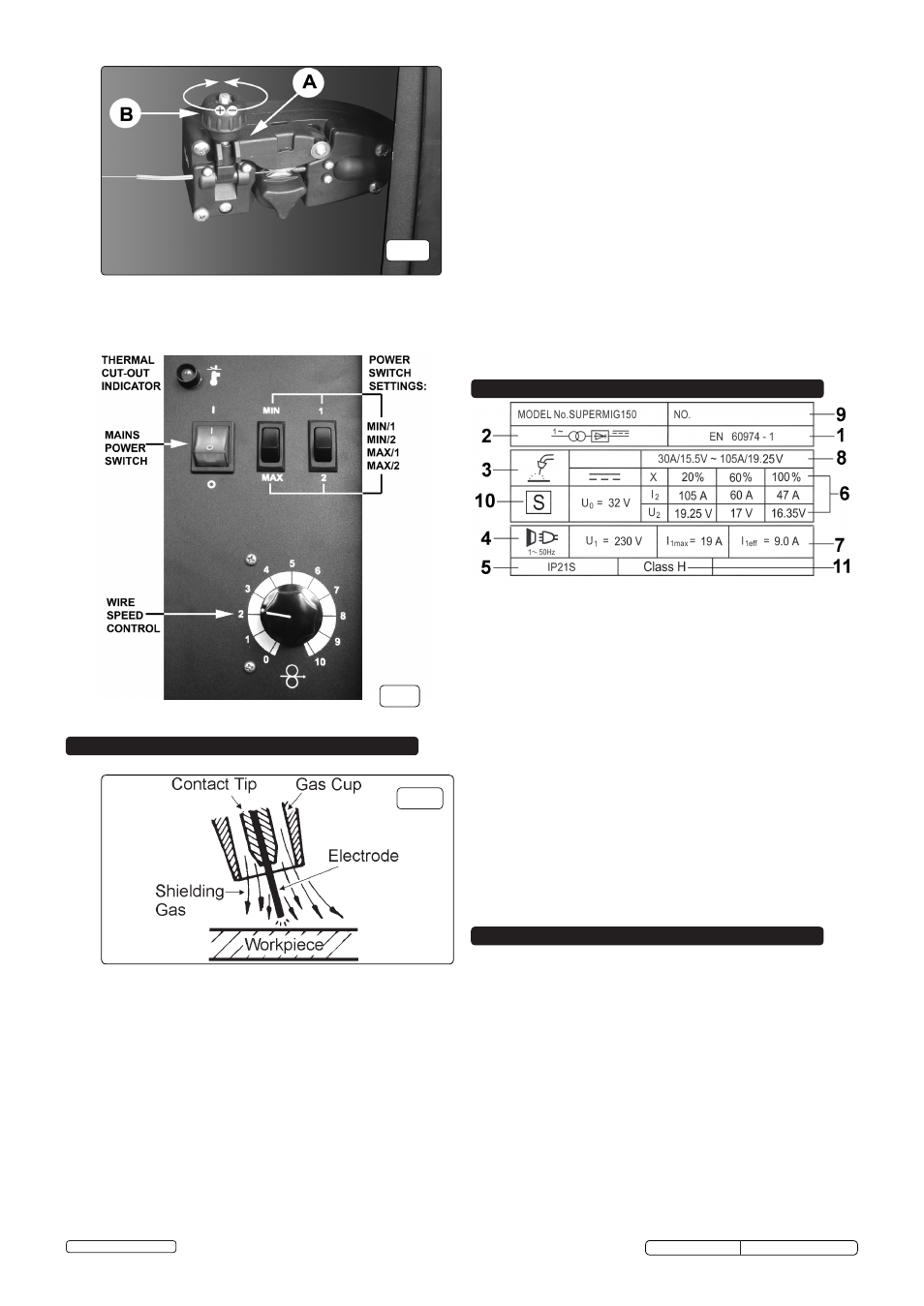
On the front panel of the welder is the rating plate, giving the following
data:
1 - The BS/EU standard relating to the safety and construction of
arc welding and associated equipment.
2 - Inverter-transformer-rectifier symbols
3 - Symbol indicates welding with a continuous flow of welding wire.
4 - Symbol for Single-phase AC supply.
5 - Rating of internal protection provided by casing.
6 - Output
U
0
: Maximum open-circuit voltage.
I
2
, U
2
: Current and corresponding voltage.
X: Welding ratio based on a 10 minute cycle. 20% indicates 2
minutes welding and 8 minutes rest, 100% would indicates continuous
welding.
7 - Mains Supply U
1
: Rated supply voltage and frequency.
I
1
max: Maximum current. I
1
eff: Maximum effective current.
8 - A/V - A/V: Welding current adjustment range and corresponding voltages.
9 - Serial Number. Specifically identifies each welder.
10- Symbol for welding power sources which are suitable for supplying
power to welding operations carried out in an environment with
increased risk of electric shock (if applicable).
11- Insulation Class.