Fig.19, Fig.20, Commencing welding – Sealey POWERMIG3525 User Manual
Page 7
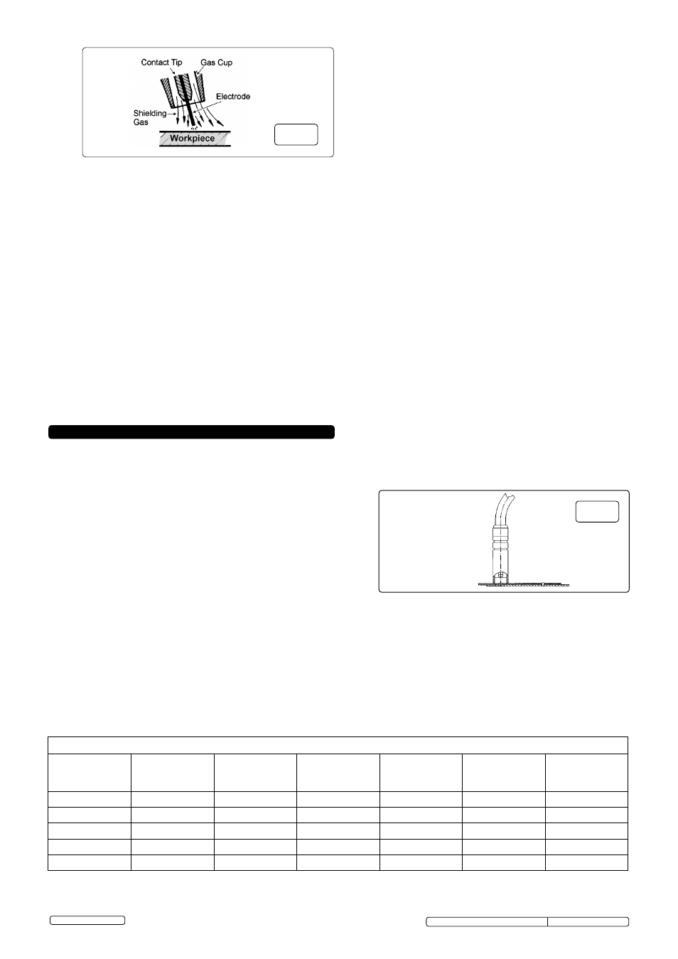
9. COMMENCING WELDING
Original Language Version
© Jack Sealey Limited
fig.19
8.2
Preparation for welding.
IMPORTANT:
BEFORE YOU COMMENCE, MAKE SURE THE
MACHINE IS SWITCHED OFF AT THE MAINS. IF WELDING A
VEHICLE, DISCONNECT THE BATTERY OR FIT AN ELECTRONIC
CIRCUIT PROTECTOR. ENSURE YOU READ AND UNDERSTAND
THE SAFETY INSTRUCTIONS IN CHAPTER 1.
8.2.1
Connecting the Earth Lead.
Connect the earth lead as described in section 5.5.
To ensure a complete circuit, the earth lead clamp must be securely
attached to the workpiece that is to be welded.
a) Best connection is obtained by grinding the point of contact on the
workpiece before connecting clamp to the workpiece.
b) The weld area must also be free of paint, rust, grease, etc.
c) If welding a vehicle, disconnect vehicle battery or fit an “Electronic
Circuit Protector” to battery, (available from your Sealey dealer).
8.2.2
The wire feed rate rotary controls are used to set the speed of the wire
feed. In principle, the lower the amperage number the slower the wire
speed.
8.3
Gas types and their use.
Welding mild steel with CO² gas is appropriate for most welding tasks
where spatter and high build up of weld do not pose a problem. To
achieve a spatter free and flat weld however, as a guideline, use an
Argon/CO² mixture. To weld aluminium use: Argon gas or Argo-
Helium mixture, 0.8mm Contact Tip, 0.8mm Aluminium Wire,
(MIG/2/KAL08)
Liner (red) Aluminium.
9.2
Aluminium Welding.
Argon or an Argon-Helium mixture should be used for shielding. The
wire used must have the same characteristics as the material to be
welded. Always use an alloy wire (i.e. aluminium/silicium);
DO NOT
use pure aluminium wire. A problem you may experience when
aluminium MIG welding is in pulling the wire for the whole length of
the torch, as aluminium has poor mechanical characteristics. The
smaller the diameter of wire the more difficult the wire feed may be.
To overcome this problem do the following.
- Use contact tip suitable for aluminium.
- Replace the wire puller rollers with aluminium compatible rollers.
- Replace the steel guide hose for wire feed with a Teflon guide hose.
- For more information contact your local Sealey dealer .
9.3
SPOT WELDING (fig.20)
9.3.1
Ensure that the welding mode switch is set to the 'SPOT' welding
position.
9.3.2
This model has the capabilty to spot weld two overlapping metal
sheets and is equipped with an adjustable timer which allows ideal
spot welding time to be set and therefore the creation of spot-welds
which have the same characteristics. In order to use the machine for
spot welding, it should be set-up as follows:
9.3.3
Replace the nozzle of the torch with the nozzle required for spot
welding. The castellations on the cup keep it the correct distance from
the weld pool and allow the shielding gas to escape. The nozzle is
also used to push the two pieces being welded together.
9.3.4
Set the rotary current adjustment switch / switches to the highest
setting.
Set the wire feed speed at almost maximum speed.
Turn ON the Timer control and set the spot welding time according to
the thickness of the metal sheets.
9.3.5
To carry out the spot welding; rest the nozzle of the torch on the
surface of the first metal sheet, then press the torch button to start
welding: the wire will melt the first sheet, pass through this sheet
and into the second, making a molten wedge between the two metal
sheets.
9.3.6
The torch button should be pressed until the timer interrupts the
welding. This system allows spot-welding to be carried out which
would not normally be possible with conventional spot welders, since
metal sheets can be joined which do not allow access to the rear side
of the workpiece.
This system also makes the operator's work much easier thanks to the
extremely light-weight torch in comparison to conventional spot welding
equipment.
The application limits of this system depend on the thickness of
the first metal sheet; the second sheet may be thicker.
9.1
COMMENCING WELDING.
9.1.1
Ensure that the welding mode switch is set to the 'CONTINUITY'
welding position.
9.1.2
Before carrying out difficult sections of welding, tests should be
carried out on scrap pieces of metal. These tests should be carried
out to find the best control settings in order to obtain the best welding
result. As a starting point refer to the welding guide below. If the arc
melts in drops and tends to go out, the speed of the wire should be
increased or the welding current decreased. If, however, the wire hits
the piece violently and causes material to be projected, the wire
speed should be reduced.
9.1.3
It should be remembered that in order to obtain the best results, each
type of wire is suited to a specific current and wire feed speed.
Therefore, for difficult sections of welding and welding which requires
a great deal of time, wires with different diameters should be tried so
that the most suitable may be chosen.
9.1.4
Turn on and adjust the protective gas using the pressure regulator.
Adjust to a flow rate of 5-7 l/min.
9.1.5 NOTE: At the end of the job, remember to turn off the protective gas.
9.1.6
Switch the welder on and set the welding current by means of
the rotary switches and by referring to the welding reference table
below .
9.1.7
Ensure that the earth clamp is in contact with the workpiece.
9.1.8
Press the torch button, keeping the torch at a safe distance from the
workpiece.
fig.20
WELDING REFERENCE TABLE (for general guidance only)
Material
Thickness
(mm)
Wire
Diameter
(mm)
Liner Inner
Diameter
(mm)
Liner
Specification
(mm)
Current
(Amps)
Voltage
(Volts)
Gas Flow
(l/min)
0.8 to 1.5
Ш0.8
Ш1.4
1.2 x 1.6 (blue)
50 to 90
17 to 18
6
1.0 to 2.5
Ш0.8
Ш1.4
1.2 x 1.6 (blue)
60 to 100
18 to 19
7
2.5 to 4.0
Ш0.8
Ш1.4
1.2 x 1.6 (blue)
100 to 140
21 to 24
8
2.0 to 5.0
Ш1.0
Ш1.6
1.2 x 1.8 (black)
70 to 120
19 to 21
9
5.0 to 10
Ш1.0
Ш1.6
1.2 x 1.8 (black)
120 to 170
23 to 26
10
POWERMIG3525, POWERMIG3530 Issue: 3 (SP) -18/07/13