Crb-631 - installation, Iso-a, Iso-b – Silvercrest CRB-631 User Manual
Page 12
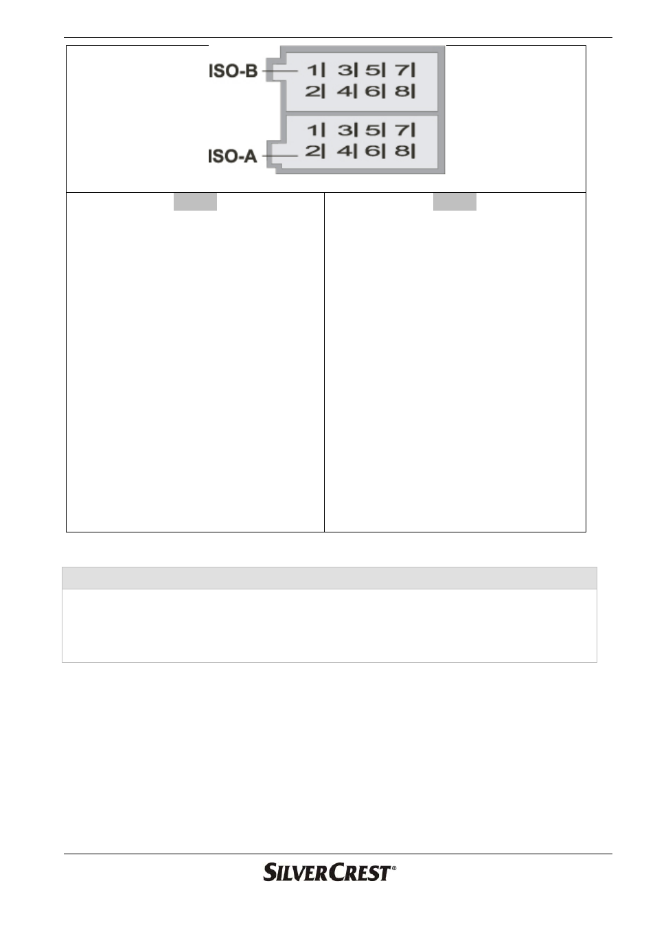
CRB-631 - Installation
12
ISO-A
A4
Yellow B+
12 V, direct battery
connection.
A5
Blue
For the control input of an
external amplifier or to the
automatic antenna (max. 100 mA /
12 V).
A6
Orange
For dimmer control
terminal. (If the headlights are
switched on, the display lighting is
dimmed)
A7
Red ACC
. Connection of the
positive pole controlled by the
ignition key/switch (12 V).
A8
GND (ground) For an effective
ground connection to the vehicle
ISO-B
Front speakers
B3 Right
+
(grey)
B4 Right
–
(grey/black)
B5 Left
+
(white)
B6 Left –
(white/black)
Rear speakers
B1 Right
+
(purple)
B2 Right
–
(purple/black)
B7 Left
+
(green)
B8 Left –
(green/black)
Note on the assignment of the ISO-A connector
The diagram shows the most common pin assignment. Several car manufacturers
such as VW, Audi, Opel and Vauxhall reverse pins A7 and A4, and the preset
channels and other programmed settings are lost when the ignition is switched off.
For this reason follow the instructions given in your vehicle manual.