Ducts for kit comfort air, Air inlet for natural ventilation, Air inlet for forced ventilation 4.6.3.1 – MCZ Forma PURO 115 User Manual
Page 17
Chapter 4
INSTALLATION AND USE MANUAL
page
17
Installation and assembly
Technical service – MCZ S.p.A. all rights reserved - Reproduction prohibited
4.6. EXTERNAL AND INTERNAL AIR INTAKE
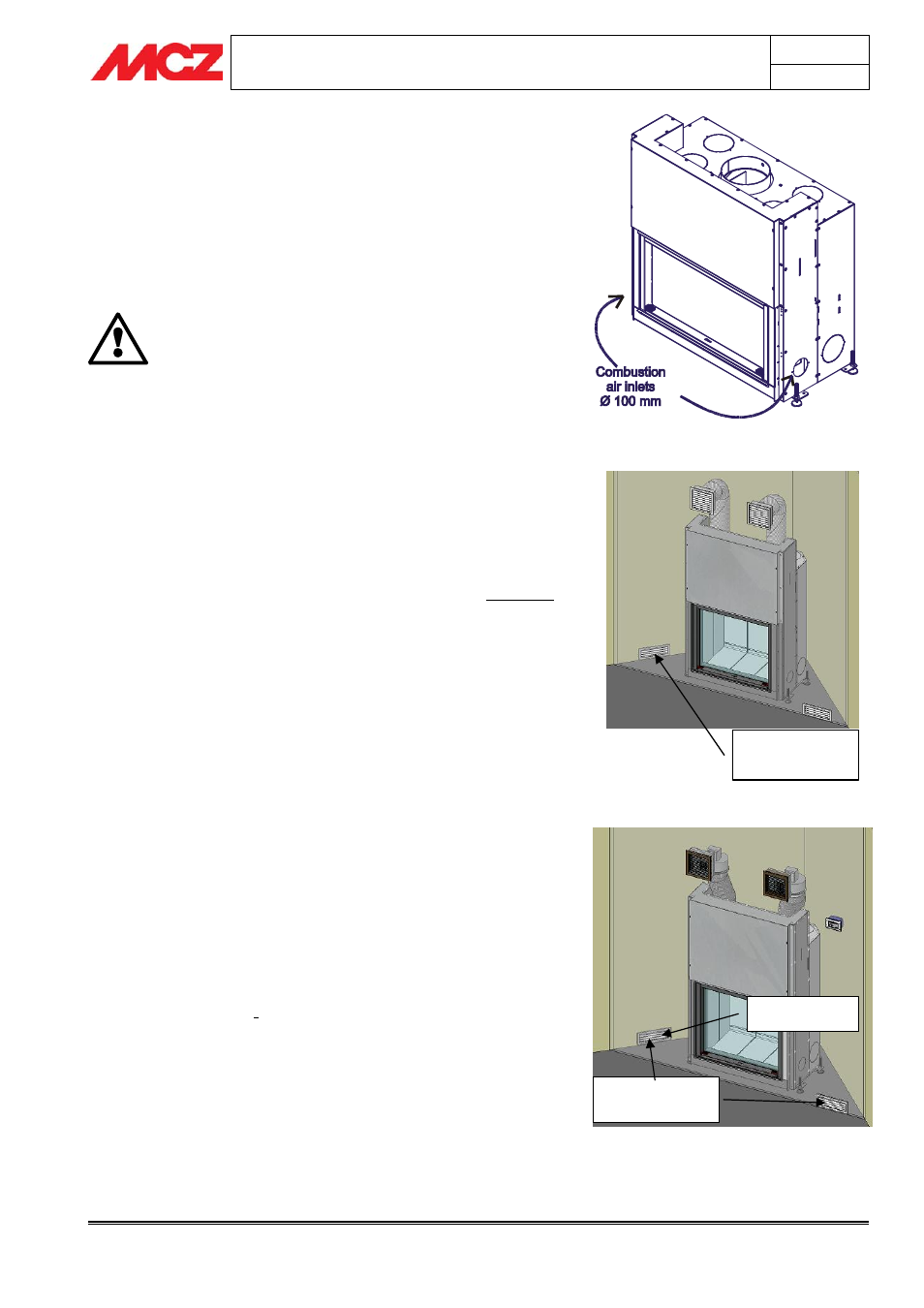
4.6.1. Combustion air inlet
The FORMA fireplace stove is set up with two side holes Ø 100 mm,
already opened, for the entry of air required for combustion.
Connect by flanges ø100 and hose at least one of the combustion air
inlets (fig. 4) grilles inside or outside the room of installation so that the
path is separate from the air of natural or forced convection.
NEVER CLOSE OFF THE COMBUSTION AIR INTAKE
HOLES.
WHEN INSTALLING THE CLADDING, MAKE SURE
THAT NONE OF ITS PARTS OBSTRUCT THE AIR
INTAKES
CONNECT AT LEAST ONE OF THE TWO DUCTS AND
ALWAYS RUN IT OUTSIDE THE CLADDING OF THE
FIREPLACE STOVE. IF YOU DO NOT COMPLY WITH
THIS RULE, THE COMFORT AIR KIT MAY DRAW IN
THE AIR INTENDED FOR COMBUSTION
4.6.2. Air inlet for natural ventilation
If the fireplace stove is installed with natural ventilation, i.e. with no
electric fan, make an external combustion air intake of 300 cm² net
behind the unit so that fresh air always flows beneath the fireplace
stove.
(figure 5)
You must comply with this instruction fully, because otherwise a lack of
oxygen may compromise combustion and calorific energy of the
product.
4.6.3. Air inlet for forced ventilation
4.6.3.1.
Ducts for kit COMFORT AIR
If the fireplace stove is installed with forced ventilation, i.e. using the
Comfort Air kit, place air intakes and ducts as follows:
for proper air circulation in the room, it is advisable to arrange one
external air intake A of 150 cm², in order to draw in clean, fresh
air; place the other B in the room where the fireplace stove is
installed (also of 150 cm²).
This mode allows a proper mix of the air in the room of installation
and better cooling of the structure of the fireplace stove.
(Figure 6)
If you cannot make this kind of connection, you will still need to
arrange both air intakes, whether they are both directed to the exterior
or the interior. Depending on the selection, you will have operating
temperatures that are slightly above or below average but which do not
compromise proper operation of the product.
Figure 5 – Intake for external combustion air
and for natural ventilation
Figure 6 – Air intakes for ducts of fan and
combustion air intake.
Air intake of 300 cm
2
for
combustion air and natural
convection
Internal and external air
intakes of 150 cm
2
for
forced ventilation air.
Combustion air intake of
150 cm
2
Figure 4 – Combustion air intakes.
A
B