Stroke adjustment – Marwin Valve UT Series Pneumatic Actuators User Manual
Page 5
-5-
5.
Push the pistons (11) into the body (1) until the piston teeth are stopped by the teeth of the pinion (2).
6.
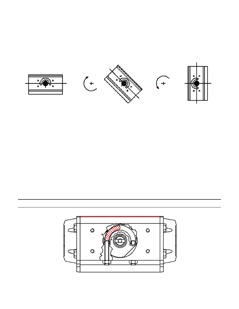
Keeping a soft pressure with the hands on the pistons (11), rotate the body (1) in clockwise rotation in respect
to the pinion (2) until feeling two clicks, when the pistons engage with the pinion (2).
7.
Now rotate the body (1) in counterclockwise rotation, and verify that at the end of the rotation the two pinion
flat surfaces are about 7° rotated to the axis of the body.
Note: Correct assembly gives symmetric stroke of the pistons, which can be verified by measuring distance
from each end face of the body. These distances should be equal.
8.
Assemble the cam spacer ring (6) and the cam (7).
9.
Assemble the pinion washer (9) and insert the snap ring (10) in its place on the pinion (2). NOTE: Use snap
rings with reinforced thickness DIN 471 - UNI 7436.
10. Proceed making the adjustment of the stroke, acting on adjusting screws (16), fixing their position securing the
nuts (15).
FOR DOUBLE ACTING ACTUATORS
11. Assemble the end caps (19,20) to the body (1) with the screws (22), using a diagonal bolting pattern.
FOR SPRING RETURN ACTUATORS
12. With the pistons in the CLOSED position, insert the springs in spring set (M) into the body (1), putting them
in the piston (11) recess. Then assemble the end cap (19) on the springs. Center the end cap recess on the
springs. Assemble the screws (22), using a diagonal bolting pattern to tighten each screw a little at a time, so
that the springs are uniformly compressed, until end cap (19) is completely closed.
13. Repeat the operation on the other side.
14. Operate the actuator to verify the correct functioning before re-installing it.
Stroke Adjustment
The left stop bolt adjusts the OPEN valve position for STANDARD (direct) rotation, and the closed valve position for
reverse rotation.