Marwin Valve UT Series Pneumatic Actuators User Manual
Page 6
3170 Wasson Road • Cincinnati, OH 45209 USA
Phone 513-533-5600 • Fax 513-871-0105
[email protected] • www.marwinvalve.com
Bulletin IM-UT(2003Design)-1211
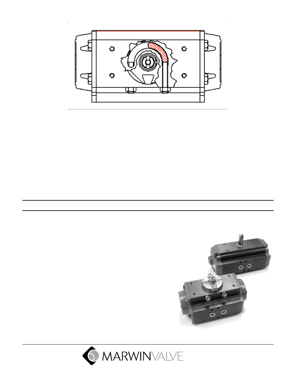
The right stop bolt adjusts the CLOSED valve position for STANDARD (direct) rotation, and the open valve position
for reverse rotation.
Stroke adjustment procedure (when pistons are in open position):
Remove air supply or move the pistons to the closed position.
Adjust the corresponding stop bolt.
Move the pistons to the open position and verify the new adjustment.
Repeat this operation until desired adjustment is achieved.
Stroke adjustment procedure (when pistons are in closed position):
Remove air supply or move the pistons to the open position (necessary for SR).
Adjust the corresponding stop bolt.
Move the pistons to the closed position and verify the new adjustment.
Repeat this operation until desired adjustment is achieved.
2003 versus Pre-2003 Design
Pre 2003 Design
UT-0 Shown
Representative of:
All UT actuators 0A thru 7 (32-270mm bore) prior to 2003
UT-0A, and UT-5 thru 7 (32 & 160-270mm bore) only after 2003
2003 Design
UT-0 Shown
Representative of:
UT Actuators 0 thru 4.5 (52-140mm bore) after 2003