Multi-Contact MA268 User Manual
Page 4
S
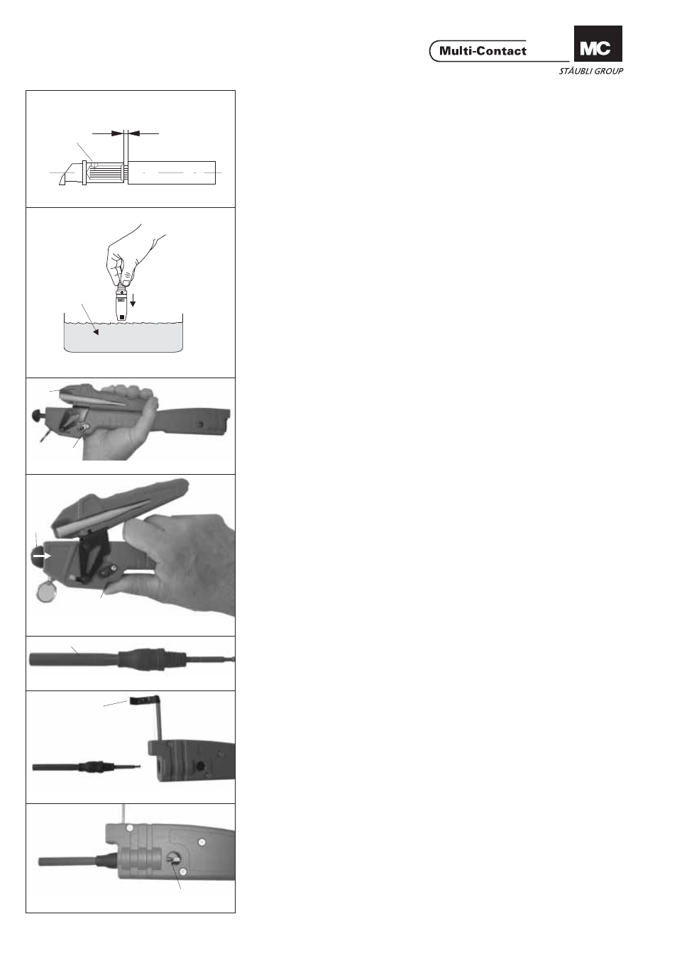
max. 1 mm
ill.6
Industriealkohol
Industrial alcohol
alcool industriel
ill.7
4/8
Montage
Assembly
Montage
(ill.7)
Der Montagevorgang
kann erleichtert werden,
wenn der Leitungausgang
der Steckverbinder-
isolation vor dem Einset-
zen der Kontakte in Indu-
striealkohol getaucht
wird.
Hinweis:
(ill.7)
Note:
To facilitate assembly, the
insulation of the plug con-
nectors may be immersed
in industrial alcohol before
inserting the contacts.
(ill.7)
Remarque:
L’emmanchement des
contacts peut être facilité
en plongeant au préalable
les corps isolants dans de
l’alcool industriel.
www.multi-contact.com
Advanced Contact Technology
(ill.8)
Betätigungshebel 3 in ge-
schlossene Stellung brin-
gen. Verschluss 7 öffnen,
Betätigungshebel 3 lösen.
Werkzeug öffnet selbst-
ständig.
3
7
ill.8
ill.9
5
4
(ill.9)
Arretierhebel 4 öffnen
und Zugstange 5 in Pfeil-
richtung in das Aufzieh-
werkzeug hineinstossen.
Kabelklemmung 1 heraus
ziehen und nach oben
klappen (siehe ill.11).
ill.10
(ill.10)
Passenden Aufweitdorn 6
auswählen und aus Maga-
zin entnehmen. Aufweit-
dorn 6 kabelseitig durch
die Isolation führen.
6
ill.11
(ill.11)
Bestückten Aufweitdorn
6 in Werkzeug einführen
1
ill.12
(ill.12)
Kupplungskopf des Auf-
weitdorn in die Führung
der Zug- und Rückstell-
stange einhängen, das
Einhängen kann über das
Sichtfenster F kontrolliert
werden.
F
(ill.8)
Place operating lever 3 in
closed position.
Open latch 7, release ope-
rating lever 3.
Tool opens automatically.
(ill.8)
Mettre le levier de com-
mande 3 en position fer-
mée.
Ouvrir le verrou 7, relâ-
cher le levier de comman-
de 3. L'outil s'ouvre de
lui-même.
(ill.9)
Open locking lever 4 and
push puller rod 5 into the
insulator mounting tool in
the direction of the arrow.
Pull out cable grip and hin-
ge upwards (see ill.11.)
(ill.9)
Ouvrir le levier d'arrêt 4 et
enfoncer la tige de tracti-
on 5 dans l'outil de mon-
tage dans la direction de
la flèche.
Sortir le serre-câble 1 et
le rabattre vers le haut
(voir ill.11).
(ill.10)
Select suitable dilator
spindle 6 and take out of
magazine.
Guide dilator spindle 6
through the insulator from
the cable side.
(ill.10)
Sélectionner un cône 6 ap-
proprié et le retirer du ma-
gasin.
Faire passer le cône 6 à
travers l'isolation côté câ-
ble.
(ill.11)
Insert dilator spindle with
insulator 6 into tool
(ill.11)
Introduire le cône 6 équi-
pé dans l'outil.
(ill.12)
Insert coupling head of
the dilator spindle into the
guide of the puller rod, en-
gagement can be che-
cked by viewing through
window F.
(ill.12)
Accrocher la tête d'accou-
plement du cône dans le
guide de la tige de tracti-
on et de rappel, contrôler
l'accrochage par la fenê-
tre F.