Multi-Contact MA268 User Manual
Page 6
ill.18
6/8
(ill.18)
Durch leichtes Ziehen an
der Leitung sicherstellen,
dass die Tülle auf dem Me-
tallteil richtig eingerastet
ist.
Bei richtiger Einbaulage
müssen die eingebauten
Teile mit der Isolations-
Stirnseite fluchten.
Beiliegender Aufkleber
“
” in der Nähe des
PV-Kupplungssteckers an-
bringen.
DANGER DO NOT
DISCONNECT UNDER
LOAD
(ill.18)
Make sure the insulator is
properly engaged on the
metal part. If the parts ha-
ve been assembled cor-
rectly, they will be flush
with the end of the insula-
tor.
Attach enclosed sticker
“
” as near as possi-
ble to the male cable
coupler.
DANGER DO NOT
DISCONNECT UNDER
LOAD
(ill.18)
S’assurer que l’isolant est
correctement monté sur la
pièce métallique en tirant
légèrement le câble.
Les pièces métalliques doi-
vent être à fleur de la face
avant de l’isolant.
Coller l’étiquette
“
” à proximité du rac-
cord mâle PV.
DANGER DO NOT
DISCONNECT UNDER
LOAD
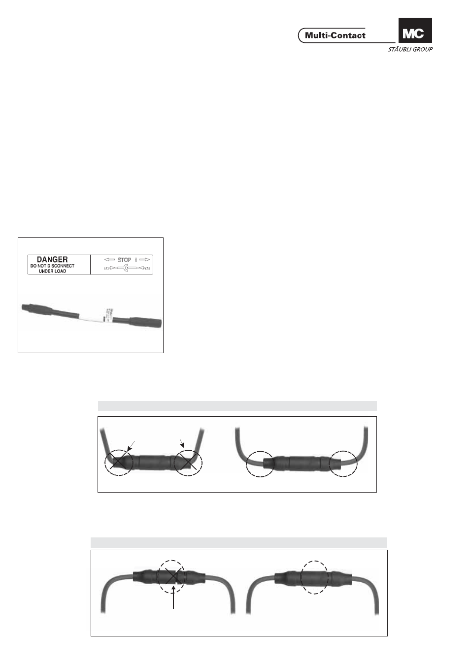
Leitungsführung / Cable routing* / Disposition de câble:
SHARP RADIUS
INCORRECT Routing of cable
CORRECT Routing of cable
GAP
INCORRECT Engagement
CORRECT Engagement
* Beachten Sie die Spezifikationen des Leitungsherstellers betreffend Biegeradius
* Refer to cable manufactures specification for minimum bending radius.
* Se référer aux spécifications du fabricant de câbles pour un rayon de courbure minimal
Verbindung / Engagement / Connexion:
ь
ь
ь
Leitungsführung * / Cable routing * / Disposition de câble *:
www.multi-contact.com
Advanced Contact Technology
- Das wiederholte Betätigen kann beendet
werden, wenn kein spürbarer Widerstand
am Betätigungshebel 3 mehr vorhanden
ist.
- Anschliessend Kabelklemmung 1 vom Ka-
bel entfernen
- Kabel mit aufgezogener Isolation aus
dem Werkzeug entfernen
- Kontrolle des ordnungsgemässen Sitzes
der Isolation gemäss Herstellerangaben
- Arretierhebel 4 öffnen und Zug- und Rück-
stellstange 5 vorsichtig in das Werkzeug
hinein schieben
- Aufweitdorn 6 von der Aufnahme der
Zugstange 5 entfernen und weitere Isolati-
on aufziehen (Ablauf beginnend mit ill.8
oder Aufweitdorn 6 zur Aufbewahrung in
das Magazin einlegen und Kabelklem-
mung 1 in Werkzeug einschieben
- Betätigungshebel 3 im geschlossenem
Zustand mit Verschluss 7 verriegeln.
- The actuation of the operating lever 3 can
be stopped when no further resistance to
its movement can be felt.
- Then remove cable clip 1 from cable
- Remove cable with fitted insulator from
tool.
- Check that the insulator is properly in pla-
ce in accordance with the maker's specifi-
cations.
- Open locking lever 4 and carefully push
the puller rod 5 into the tool.
- Remove dilator spindle 6 from the mount
of the puller rod 5 and fit another insulator
(procedure beginning with ill. 8), or place di-
lator spindle 6 in the magazine for storage
and push cable grip 1 into tool.
- Lock operating lever 3 in closed position
with latch 7
- On peut arrêter l'actionnement répété
quand plus aucune résistance n'est per-
ceptible sur le levier de commande 3.
- Détacher ensuite le serre-câble 1 du câ-
ble
- Retirer le câble avec l'isolation montée de
l'outil
- Contrôler le montage correct de l'isolati-
on conformément aux indications du fabri-
cant
- Ouvrir le levier d'arrêt 4 et enfoncer avec
précaution la tige de traction et de rappel 5
dans l'outil
- Retirer le cône 6 du logement de la tige
de traction 5 et monter une autre isolation
(en commençant à l'ill.8) ou ranger le cône
6 dans le magasin et enfoncer le serre-
câble 1 dans l'outil
- Verrouiller le levier de commande 3 en po-
sition fermée avec le verrou 7.