Gt control panel, Lumin8 installation instructions 8 – RISCO Group Lumin8 User Manual
Page 8
LuMIN8 Installation Instructions
8
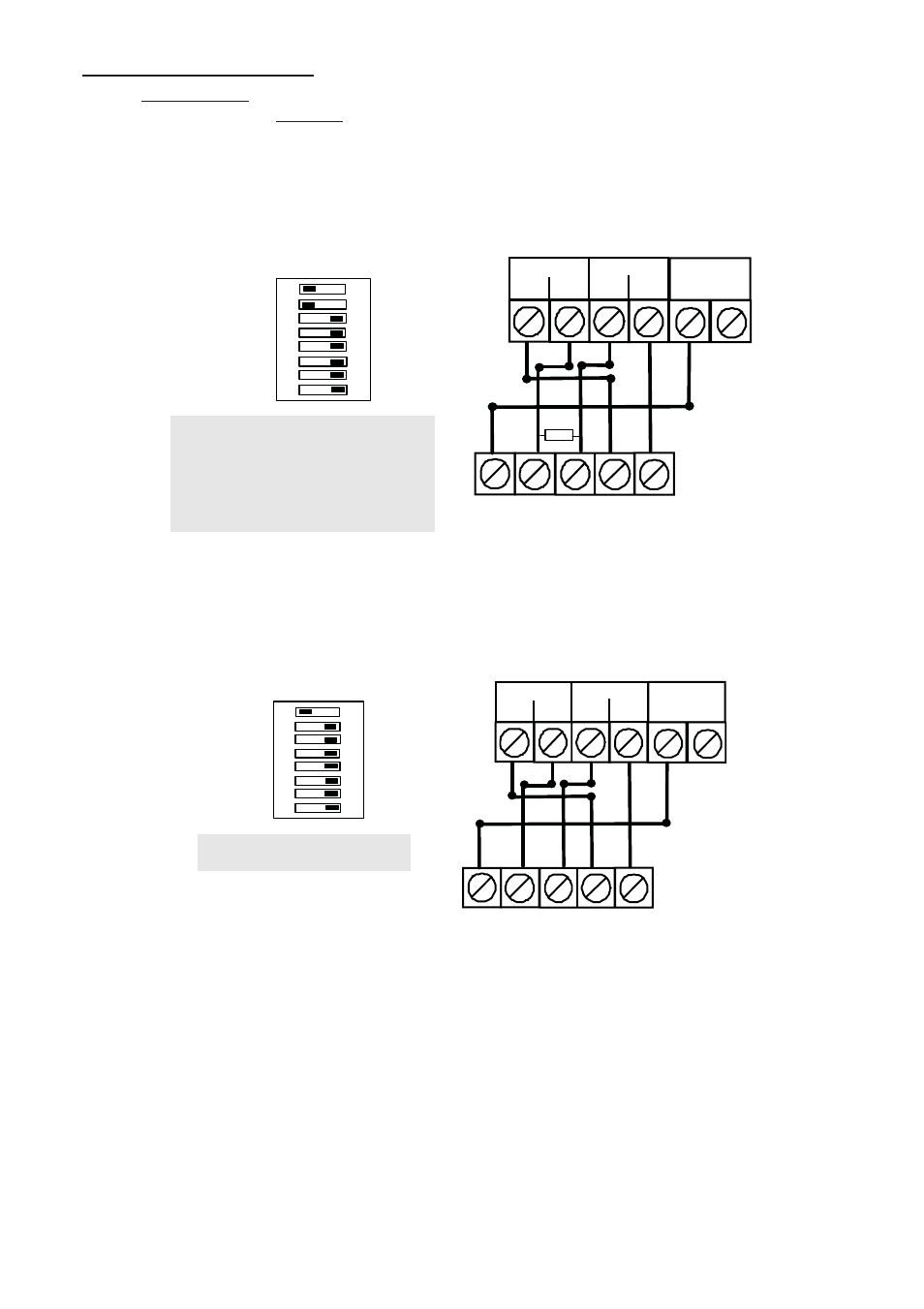
! Monitored Positive Trigger.
On the Control Panel fit a 1K resistor (or 2 x 2K2 resistors in parallel) between the Trigger positive
terminal and 0V. On the Sounder set SW6 (+ve trigger select) and SW7 to ON (4K7 resistor
between the TRIG terminal and the Hold – terminal). Connect Switched 12V Positive Trigger signal
from Control Panel to TRIG terminal on Sounder.
Monitored Mode Wiring for GT Panels
(Stand Alone Mode)
LuMIN8 Sounder
SW7 ON: An internal 4K7 resistor is
connected between the
TRIG terminal and the HOLD – (0V)
terminal.
SW8 ON: a short between the TMPF
terminal to HOLD – (0V).
+
-
HOLD
TMPR
TRIG
ACT BUS
STB- TMPF
+
-
BELL
BELL
HOLD
SAB
TMP
STROBE
2K2
ON
OFF
ON
OFF
ON
OFF
ON
OFF
ON
OFF
ON
OFF
ON
OFF
OFF
ON
SW1
SW2
SW3
SW4
SW5
SW6
SW7
SW8
DIPSWITCH
SCB/SAB
A1
A2
A3
BUS/STD
PRO/ACT
MON/NM
TMF/EXT
GT Control Panel
Non - Monitored Mode Wiring for GT Panels
(Stand Alone Mode)
LuMIN 8 Sounder
SW8 ON: a short between the
TMPF terminal to HOLD – (0V)
+
-
HOLD
TMPR
TRIG
ACT BUS
STB- TMPF
+
-
BELL
BELL
HOLD
SAB
TMP
STROBE
ON
OFF
ON
OFF
ON
OFF
ON
OFF
ON
OFF
ON
OFF
ON
OFF
OFF
ON
SW1
SW2
SW3
SW4
SW5
SW6
SW7
SW8
DIPSWITCH
SCB/SAB
A1
A2
A3
BUS/STD
PRO/ACT
MON/NM
TMF/EXT
GT Control Panel