ROCKINGER RO 825 B User Manual
Page 5
ROCKI NG E R
Member of JOST-World
18
1
1.. IIn
ns
stta
alllla
attiio
on
n
R
RO
O
i
i
8
82
25
5 B
B
Installation with ROCKINGER hitch bracket
RO
i
899 D and use in height adjustable ladders
For the fastening on ROCKINGER hitch bracket, type 899 D 30 with a
hole pattern 160 x100 / M 20, 4 bolts M 20 x 55 are required:
e.g. RO bolt set 74 L052
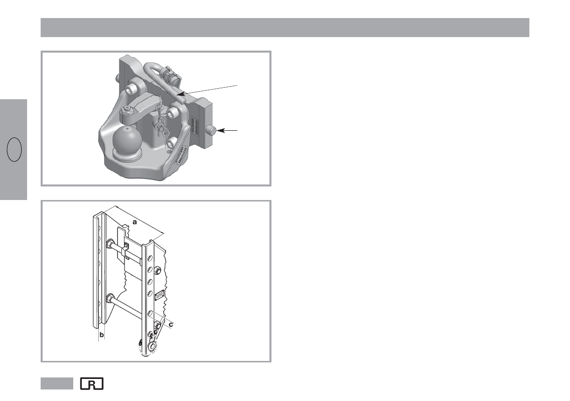
x Insert the ball coupling with hitch bracket into the guide rail of the
ladder.
x ATTENTION! Hold the coupling firmly. Risk of injury!
x Turn the hand grip (H) of the cam plate upwards and press to the
left. The arresting bolts (A) move inwards.
x Insert the coupling in the desired position in the ladder, hold it in
position and turn the hand grip (H) back to the right so that the
bolts are engaged.
x When the arresting bolts are engaged, release hand grip (H).
The hand grip must engage in the locked position.
Check:
The hand grip must be folded down, and in the locked position
it should not be possible to push it more than ca. 3 –4 mm to the left.
Fig. 4
Fig. 3
H
A
a
= Track width (mm)
b
= Groove width (mm)
c
= Bolt boring (mm)
GB