Connection diagram – Rose Electronics UltraVista Plus User Manual
Page 12
8
UltraVista Plus Installation and Operations Manual
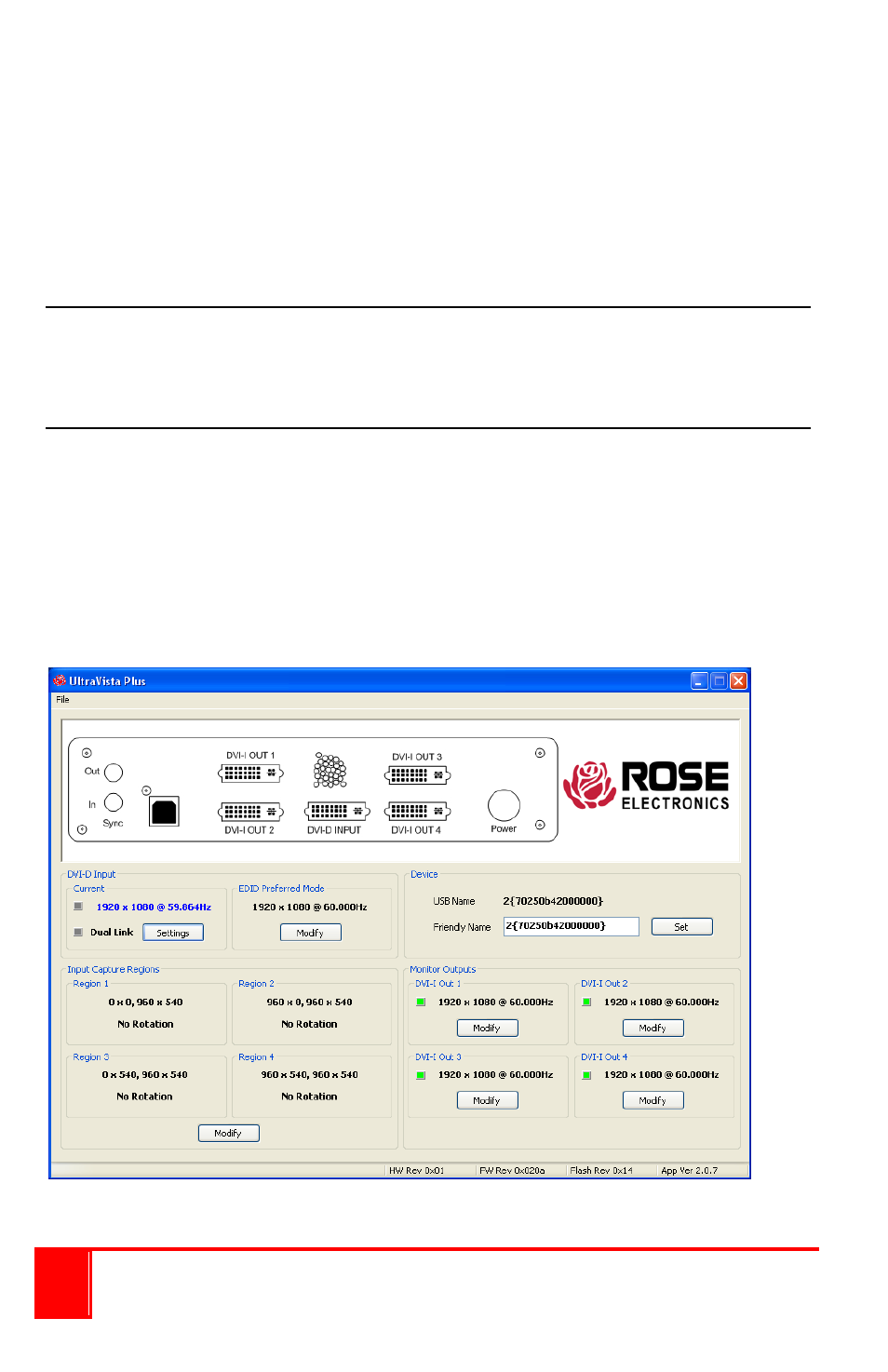
The main control application window is divided into the following groups:
Connection Diagram
Device
DVI-D Input
Input capture region
Monitor Outputs
Connection diagram
The connection diagram shows a view of the rear panel of the UltraVista
Plus.
Device section
The unique USB device name that is connected is displayed in the Device
group. It is possible to associate a more user friendly name such as “First
Four Outputs”. The friendly name is stored in non-volatile storage on the
UltraVista Plus and can to help identify the device during future
configuration sessions. Specific devices connected to your PC can be
selected using the Select Device command on the File Menu. The UltraVista
Plus’s will be listed by the USB Device or by a previously configured friendly
name.