Models, Installation – Rose Electronics UltraVista Plus User Manual
Page 7
Advertising
MODELS
UltraVista Plus Installation and Operations Manual
3
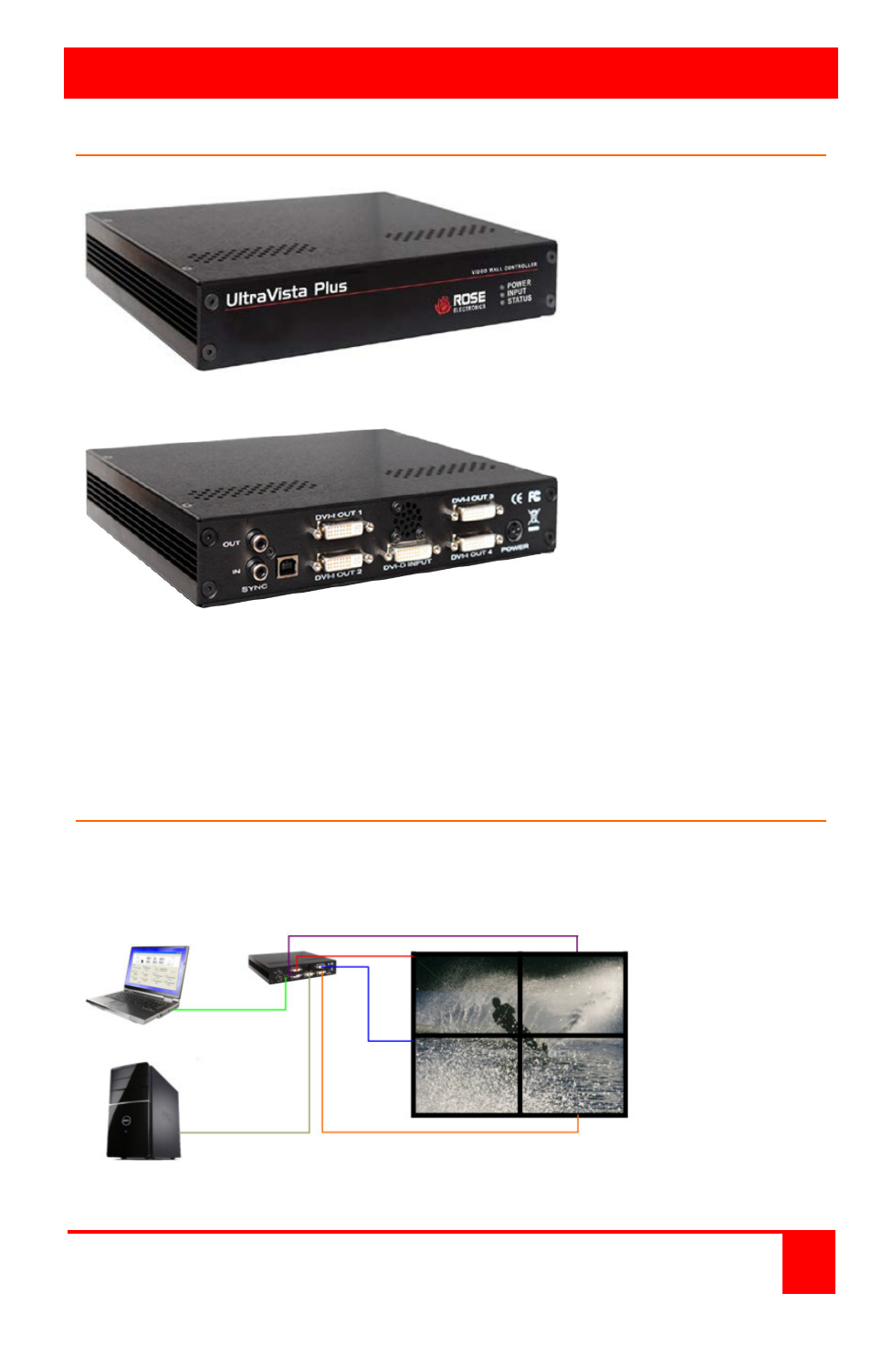
Models
Front View
Indicators
Power
Input
Status
Rear View
Connectors
Sync – For future
enhancements
USB – to control
PC via USB A/B
cable (supplied)
Input – DVI-D
Output (4) – DVI-I
Power
Figure 1. Models
Installation
Figure 2 shows a typical installation. Be sure to install the provided USB
drivers on the control computer before connecting it to the UltraVista Plus’s
USB port.
Figure 2. Typical Installation
DVI Source
Advertising