Ddc information – Rose Electronics CrystalView DVI Plus User Manual
Page 14
8
CrystalView DVI Plus Installation and Operations Manual
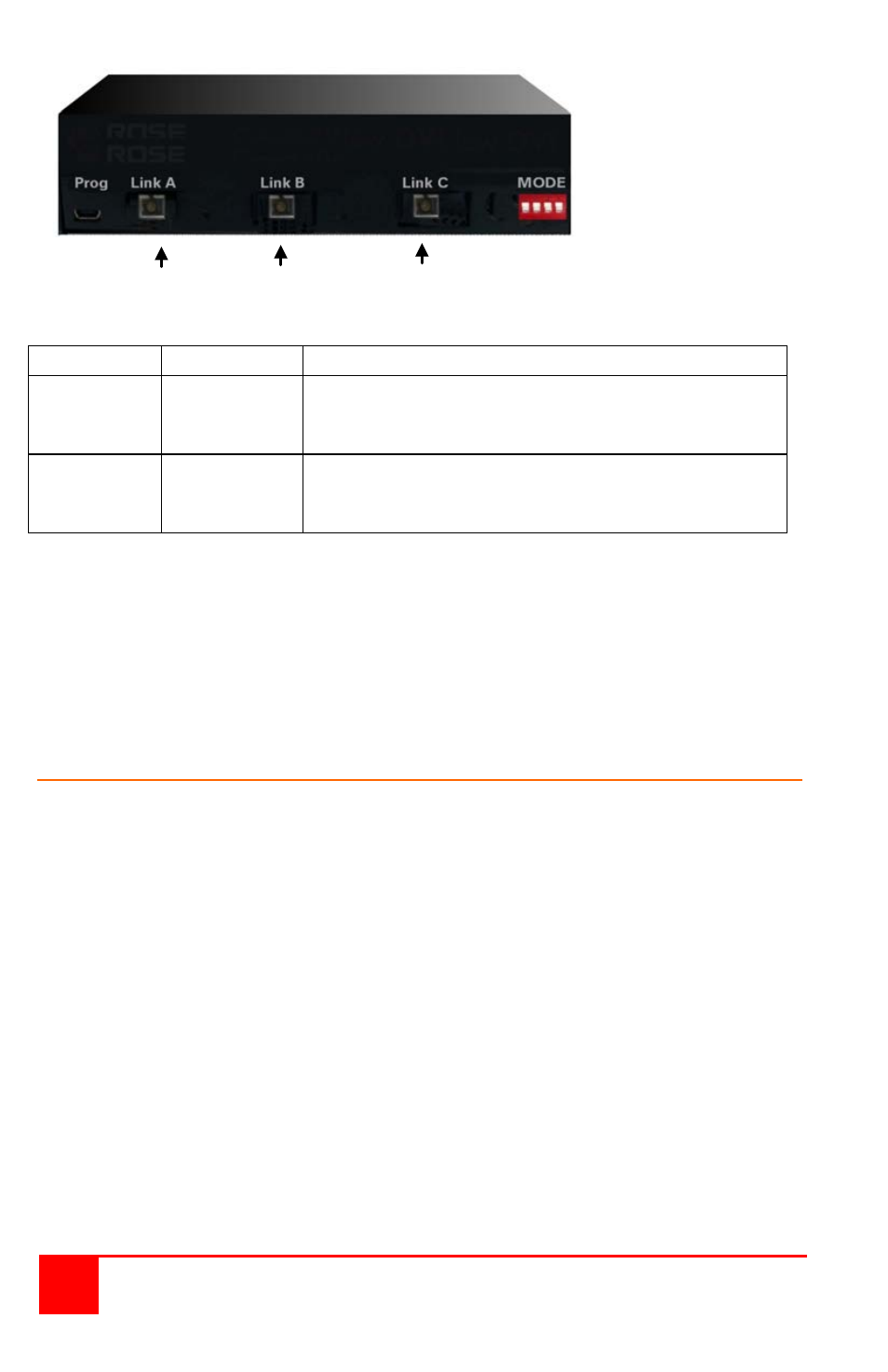
Front View
USB DVI 1 DVI 2
Fiber Fiber Fiber
LED
Status
Description
Fiber
DVI 1 & 2
(Green)
Off
On
Blinking
No connection to DVI 1 or 2
Connection to DVI 1 and 2 OK
Connection to DVI 1 or 2 disturbed
USB
(Green)
Off
On
Blinking
No connection to USB port
USB connection OK
Connection to USB port disturbed
To make sure there is a secure fiber connection, the SC plugs on the fiber
cable should snap into the sockets and the Link LEDs ON.
NOTE: The four dip switches on the front panel must be in the “OFF”
position during operation. Any other position can lead to
malfunctions during operation. These dip switches should only
be changed with specific instructions from technical support.
DDC Information
Connect all cables between CPU and Local Unit, Remote Unit and
monitor (Dualhead: BOTH monitors), Local and Remote Unit with the
interconnection cable. Power up the CPU, the Local Unit, the Remote
and the Monitor
With system power on, remove the Monitor Cable(s) from the Remote
Unit (Dualhead devices: BOTH Monitors!) – The Link LEDs must still be
illuminated.
Turn ON the Monitor(s) (if switched OFF, Dualhead devices: BOTH
Monitors!)
Connect the video cable of the Remote Monitor(s) into the remote unit
The DDC Information of the Remote Monitor(s) is read automatically,
transferred to the Local Unit and stored in the DDC-EPROM
After a successful programming of the DDC EPROM, the ‚Video-OK’
LED at the Local Unit is blinking rapidly for approx. 1 second
With some graphic cards you must reboot your CPU to make the graphic
card accept the new DDC information from the Local Unit.