2 terminals for internal use, 1 over temperature, 2 motor overload – SAF OPAL SS6 User Manual
Page 22: 3 phase loss, Terminals for internal use, Over temperature, Motor overload, Phase loss
OPAL SS6 Reduced Voltage Starters
Page 15
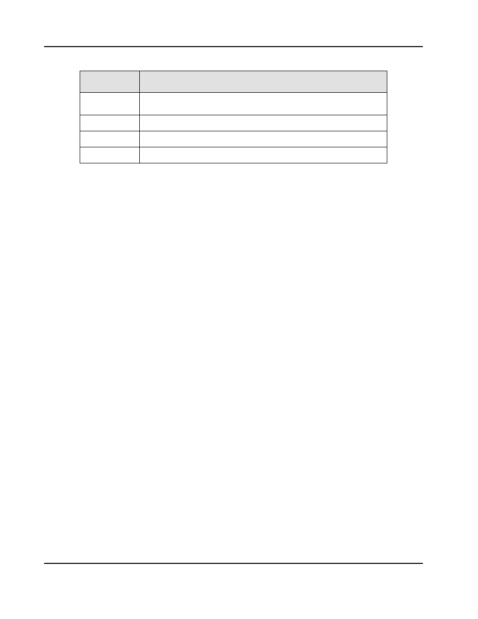
3.4.2 TERMINALS FOR INTERNAL USE
TERMINAL
DESCRIPTION
OT
This two pin connector is for an over temperature switch on
units with fans and must be shorted if an OT switch is not used
FAN
Fused 115 VAC for fan connection
SCR1-6
Gate lead connections for SCR firing
OPT
Provided for ribbon cable link to SAF's OPAL option cards
3.5 FAULTS
Any OPAL fault energizes the fault relay and shuts down the starter. Whenever any fault exists, the
READY LED will be off indicating the starter won't run. Once the fault is cleared, READY will be
illuminated if no other faults exist. Terminal TB-2 to 3 will be open when no fault exists and closed
during a fault condition, TB2 to 4 is vice versa.
3.5.1 OVER TEMPERATURE
OPAL units with fans have over temperature switches fastened to the heatsink(s). This switch or
switches in series, are connected in the OT terminal on the control card. Units without fans have
a jumper installed. In the case where there is a fan failure or fan blockage and the heatsink
temperature exceeds 85°C / 185°F ± 5°C / 41°F, the over temperature switch opens, faulting the
OPAL. This fault is indicated by LD1, OVERTEMP. When the heatsink cools enough, creating
switch closure, the OVER TEMP LED will extinguish.
3.5.2 MOTOR OVERLOAD
This fault has two conditions, instantaneous over current (IOC) or inverse timed overload. Both
of these faults are indicated by LD4, MOTOR OVRLD. If started into a short, the OPAL should
trip on an IOC dependent upon the impedance of the incoming lines. This condition is resettable
instantly by the RESET button. The inverse time overload is a class 20 overload that simulates
the heating of the motor.
This electronic circuitry begins to integrate whenever the current to the motor exceeds 115% of
the current setup with SW2. This current calibration switch should be setup to the name plate
current rating of the motor. Once the overload circuitry reaches the trip level, the unit faults and
shuts down. This trip is allowed to be cleared with the RESET button after a time period of
approximately 5-7 minutes. This time allows for the motor to cool before restarting.
3.5.3 PHASE LOSS
If any of the incoming lines are not present before starting the OPAL will be faulted. Each line is
indicated by a corresponding neon lamp. Once the missing phase(s) is/are present and no other
faults exist, the unit will be ready to run.