Figure 1-1. status reporting structure, Status reporting structure -5 – KEPCO KLR Series Developers Guide User Manual
Page 15
Advertising
KLR-DEV 060713
1-5
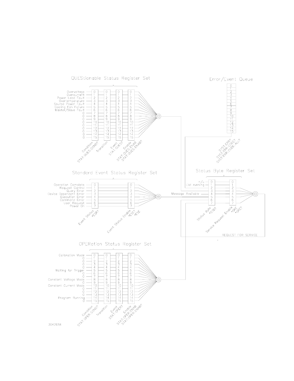
For example, if an overvoltage error is detected, bit 0 of the Questionable Status Condition reg-
ister is set. The 0 to 1 transition causes bit 0 to be stored as a 1 in the corresponding Event reg-
ister. If bit 0 of the Questionable Status Enable register has bit 0 set, bit 3 of the Status Byte
(STB) register is asserted. If bit 3 of the Service Request Enable (SRE) register is also set to 1,
then bit 6 of the STB is set to 1 (true), causing the power supply to assert the SRQ line to the
host computer.
FIGURE 1-1. STATUS REPORTING STRUCTURE
Advertising