3 changing the limit model, Changing the limit model -19 – KEPCO KLR Series Developers Guide User Manual
Page 41
Advertising
KLR-DEV 060713
3-19/(3-20 Blank)
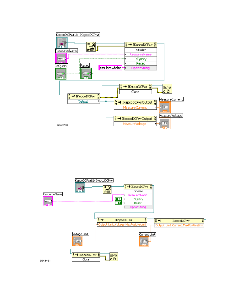
FIGURE 3-7. MEASURING VOLTAGE AND CURRENT USING LABVIEW WITH IVI-COM DRIVER
3.5.3
CHANGING THE LIMIT MODEL
The limit model Vi is very similar to the output setting and measurement examples; it has the
identical open and close functionality. The middle three blocks set the password, then cause the
voltage limit and the current limit to be applied to the KLR. This is done using the Max Positive
Current Limit and Max Positive Voltage Limit properties. As indicated in the earlier table these
are the setting nodes that are required to change the KLR limit model.
FIGURE 3-8. SETTING THE LIMIT MODEL USING LABVIEW WITH IVI-COM DRIVER
Advertising