5 remote voltage control, Remote voltage control – KEPCO RCW 1500W Series User Manual
Page 10
8
RCW 1500W 120607
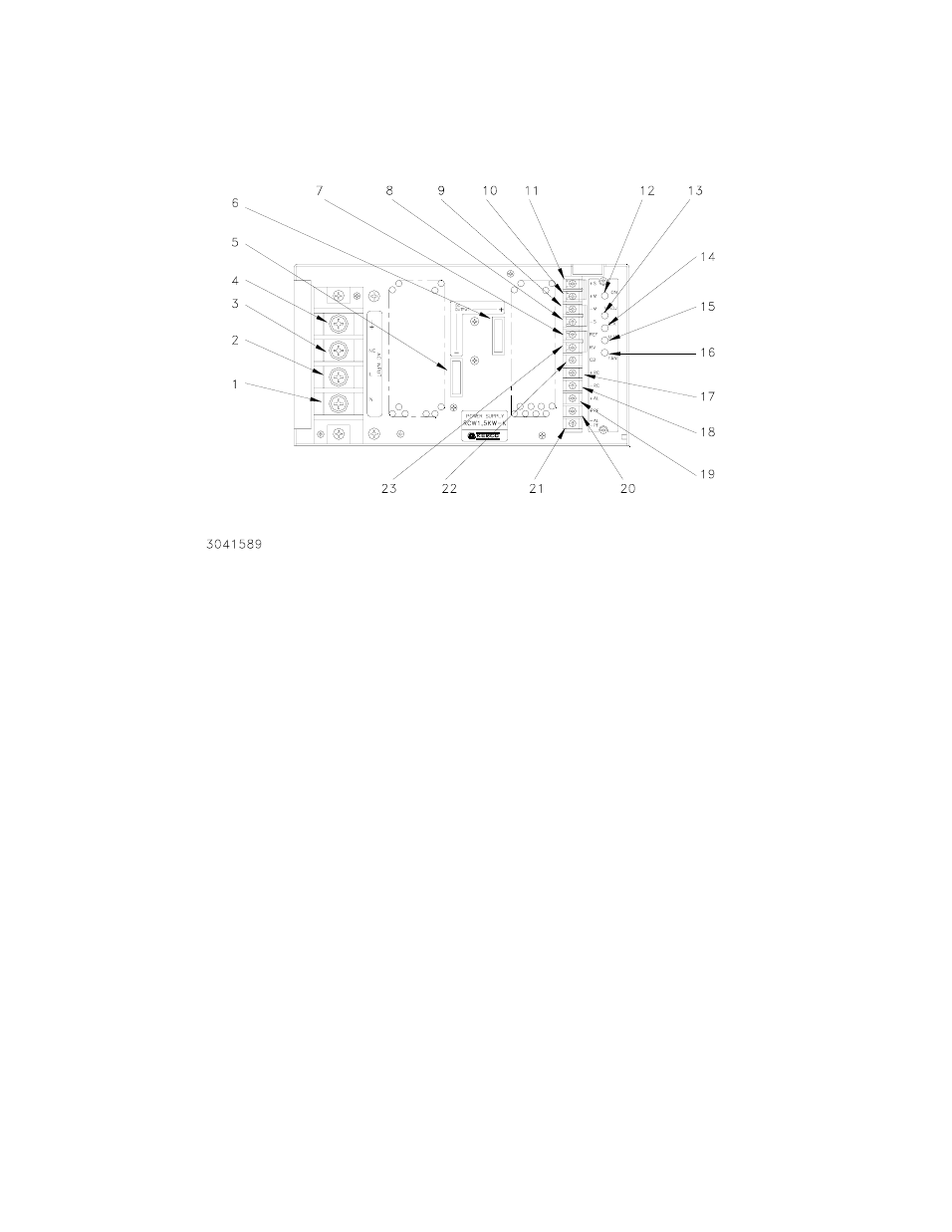
FIGURE 6 TERMINAL LOCATIONS OF THE RCW 1500W POWER SUPPLY
3.5 REMOTE VOLTAGE CONTROL
The use of the RV terminal allows the output voltage to be adjusted by a trimmer pot or by an exter-
nal source.
Use a shielded wire, 2m maximum in length, for connection to the trimmer control. Maintain the
shorting link between the (+) S and (+) M terminals, and between the (–) S and (–) M terminals,
remove links between REF and RV terminals and connect the external trimmer between the
REF,RV, and (–) M and (–) S terminals (with the center lead of the trimmer going to the RV termi-
nal, see Figure 7). Suggested value for the trimmer control is 5K ohms. With the external trim-
LEGEND:
1.
AC Input (Neutral)
2.
AC Input (Hot)
3.
No Connection
4.
Ground
5.
DC Output (–)
6.
DC Output (+)
7.
REF (Reference Voltage)
8.
(–) S (Remote Sense)
9.
(–) M (Output Voltage Monitor)
10. (+) M (Output Voltage Monitor)
11. (+) S (Remote Sense)
12. ON (Output voltage ON LED, green)
13. V. ADJ (Output Voltage Adjustment)
14. OV (Output overvoltage LED, red)
15. UV (Output undervoltage LED, red)
16. FAN (Fan alarm LED, red)
17. (+) RC (Remote ON-OFF)
18. (–) RC (Remote ON-OFF)
19. (+) AL (Alarm OV, UV, Thermal, )
20. (+) PF (Alarm- Input Power Fail)
21. (–) AL, (–) PF (Alarm common))
22. CB (Current Balance)
23. RV (Output voltage variable)