Installation instructions, Stationary fifth wheel installation, Sliding fifth wheel installation – SAF-HOLLAND XL-FW503 FleetMaster LowLube Series Fifth Wheels with Manual Sliding Secondary Lock XA-201-S10217, XA-201-S10579 & XA-231-S10217 User Manual
Page 5: Inboard angle mounting (see figures 3 and 4)
INSTALLATION INSTRUCTIONS
continued
Stationary Fifth Wheel Installation
continued
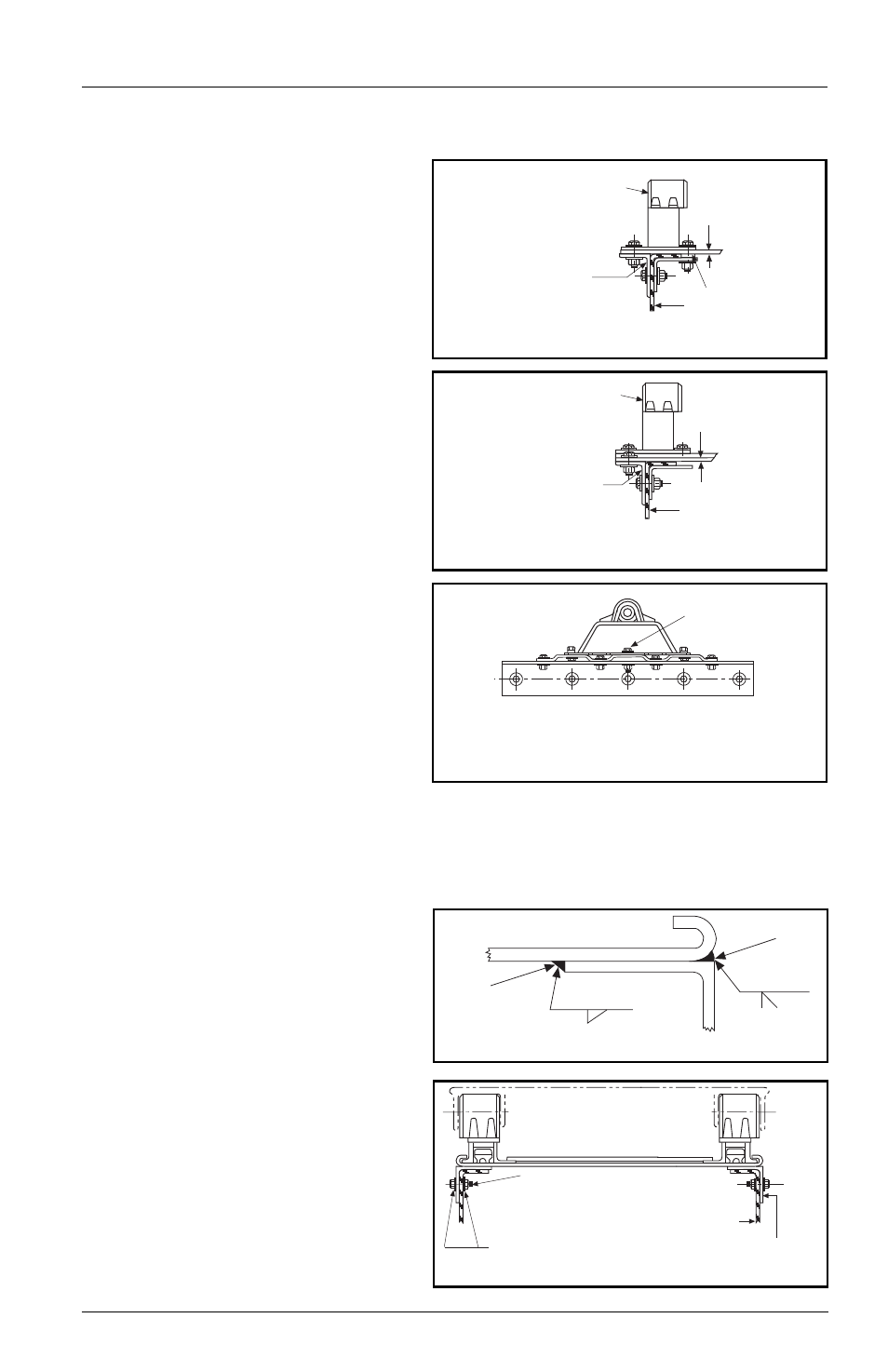
Bracket with Mounting Base
(See Figures 2A, 2B, and 2C):
1.
Holland brackets with mounting
base are intended for installation
on either corrugated or flat
mounting plates.
2.
In addition to the information
given in “Installation: General
Recommendations,” on page 3,
follow the recommendations in
FIGURES 2A, 2B, and 2C.
3.
See “Installation: General
Recommendations” on page 3
for angle thickness and material.
The mounting angle should be 1˝
longer than the mounting plate,
and be 36˝ minimum length.
Use 3˝ minimum horizontal and
3 -1/2˝ minimum vertical leg size.
Longer horizontal legs may be
required with narrow frame widths.
Sliding Fifth Wheel Installation
Prior to proceeding with the installation of the sliding fifth wheel assembly,
carefully review the “General Safety Information” section on page 2.
Inboard Angle Mounting
(See Figures 3 and 4):
1.
Angles must be installed on the
sliding fifth wheel base plate to
facilitate mounting. See “Installation:
General Recommendations,” on page
3, for angle thickness and material.
2.
Use a mounting angle which is at
least 2˝ longer than the slide base
plate and 36˝ minimum length.
Use 4˝ minimum horizontal and
3-1/2˝ minimum vertical leg size.
The fifth wheel top plate and support
bracket may be removed from the
base plate for ease of handling.
FIFTH WHEEL
SUPPORT BRACKET
FLAT MOUNTING PLATE
See Chart 1 for
minimum thickness
INBOARD ANGLE
TRACTOR FRAME
SPACER
Attach the outboard angle to
tractor frame with hardware
listed in Figure 1A. Attach
mounting plate to angle
with same number of bolts
(in addition to attachment to
fifth wheel support bracket).
Attach the outboard angle to
tractor frame with hardware
listed in Figure 1A. Attach
mounting plate to angle with
same number of bolts (in
addition to attachment to
fifth wheel support bracket).
CORRUGATED
MOUNTING PLATE
See Chart 1 for
minimum thickness
TRACTOR FRAME
FIFTH WHEEL
SUPPORT BRACKET
CENTER
BOLT
Attach bracket and mounting plate as shown.
Use center bolt of sufficient length to bolt through
bracket, mounting plate and mounting angle.
FIGURE 2C
FIGURE 2A
FIGURE 2B
3/8˝
3 - 8.50˝
5/16˝
3 - 8.50˝
INSIDE
WELD
OUTSIDE
WELD
FIGURE 3
See Chart 1 for min.
mounting angle
thickness
HARDENED STEEL
WASHERS
The full length of the fifth wheel mounting
angle should seat flush on the truck frame
when mounting to prevent flexing of
mounting angle and to give uniform
weight distribution along truck frame rail.
5/8” diameter Grade 8 bolts minimum size.
Tightening torque to bolt manufacturer charts.
Hardened steel washers or flanged locknuts.
5/8” diameter Grade “C” locknuts.
TRUCK FRAME RAIL
FIGURE 4 (End View)
XL-FW503 Rev B
5