Installation instructions, Sliding fifth wheel installation - ils slider, Inboard angle mounting – SAF-HOLLAND XL-FW492 FW83 and XA-231 FleetMaster LowLube Series Fifth Wheel User Manual
Page 9: See figures 3 and 4), Outboard angle mounting (see figures 5a and 5b)
XL-FW492 Rev D
9
INSTALLATION INSTRUCTIONS
continued
Sliding Fifth Wheel Installation - ILS Slider
continued
Inboard Angle Mounting
continued
(See Figures 3 and 4):
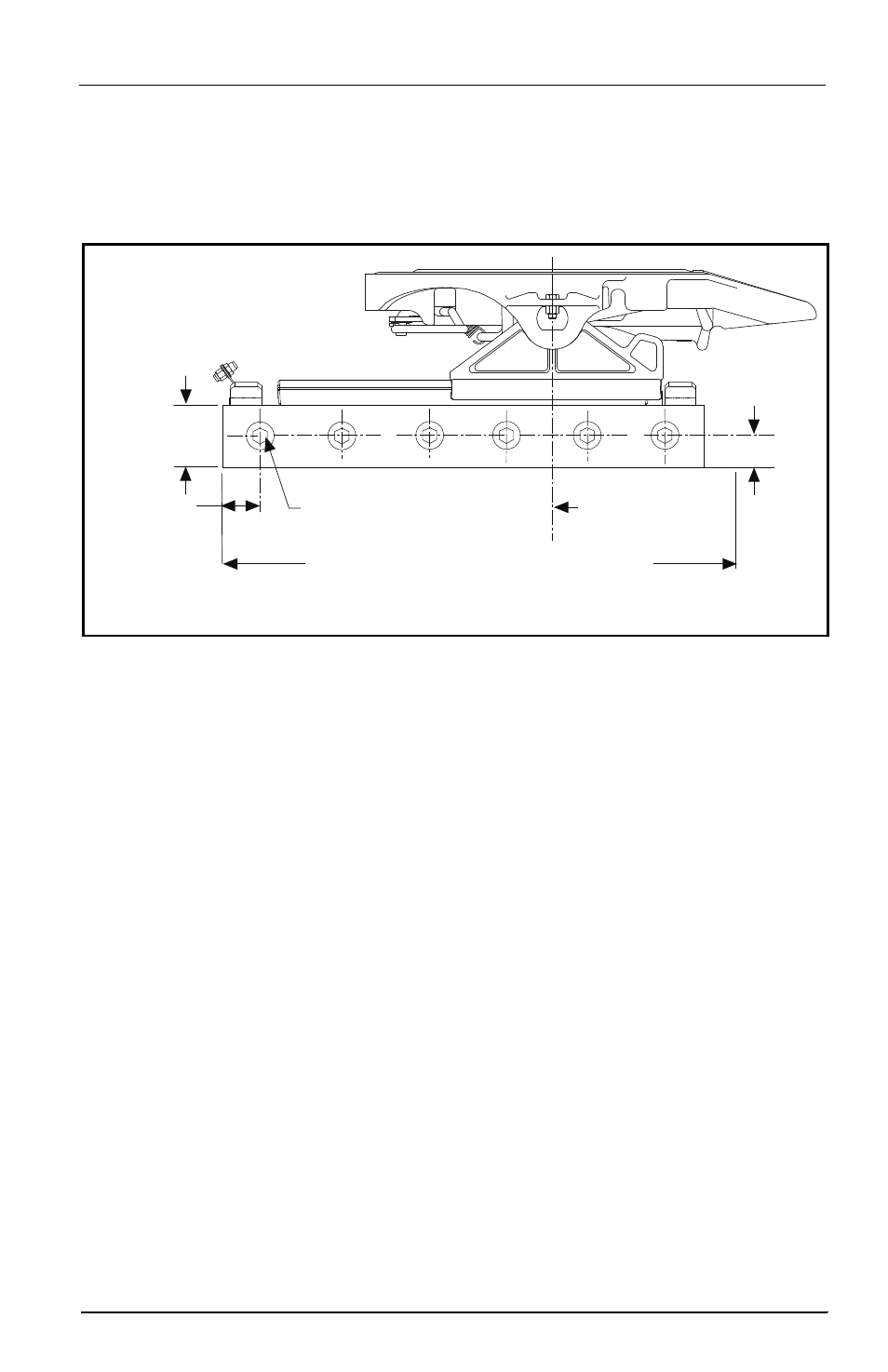
FIGURE 4 (Side View)
3.5˝ (88.9 MM)
MIN
5/8˝ min. 6 bolts
equally spaced;
hardened steel washers
1.00˝
(25.4 MM)
MIN
4.00˝
(101.6 MM)
MAX
OUTBOARD = SAME AS SLIDER LENGTH
INBOARD = SLIDER LENGTH +2.0˝
CENTER LINE OF
TRACTOR REAR
AXLE(S) OR BOGIE
Outboard Angle Mounting
(See Figures 5A and 5B):
1.
If angles are not installed, see “Installation: General Recommendations,” on page 3, for
thickness and material. Use 3˝ minimum horizontal and 3-1/2˝ minimum vertical
leg size. Longer horizontal legs may be required with narrow frame widths. The
recommended length of each mounting angle is the same length as the slide base
mounting plate.
2.
In addition to the information given in “Installation: General Recommendations,”
on page 3, follow the recommendations in FIGURE 5A. The following sequence is
suggested:
A.
Securely position the mounting angles to the tractor frame and attach as shown
in FIGURE 5A. Follow the bolting recommendations as shown in FIGURE 4.
Angles must be flush with the top of the truck frame.
B.
Locate the slide base and center left to right and front to rear on the mounting
angle. FIGURE 5B depicts distance from fifth wheel centerline to last mounting
hole, when fifth wheel is in full rear position. Clamp in place and drill 21/32˝
diameter holes using the mounting plate as a template if holes are not provided
in the angle.
C.
Align holes in the slide plate with outboard angle mounting holes and bolt
using Grade 8 fasteners, hardened steel washers and Grade C locknuts, properly
tightened, (see FIGURE 5A). Use all mounting holes on the fifth wheel.
NOTE: Tighten center nut, then alternate nuts on either side, beginning with
end nuts.