Installation instructions, Installation, Fifth wheel design and intended use – SAF-HOLLAND XL-FW488 FW2800 and FW2900 Series Hydraulic Elevating Fifth Wheel User Manual
Page 2: General recommendations
2
XL-FW488 Rev A
INSTALLATION INSTRUCTIONS
When welding, use a procedure which assures a sound, good quality
weld and which protects the operator and others. Overwelding may
cause distortion and damage, and underwelding may not develop sufficient strangth. A
low hydrogen process and AWS E70XX filler metal are recommended. Take precautions
to ensure that the tractor electrical system is not damaged by the welding.
Fifth Wheel Design and Intended Use:
1.
For pulling trailers with standard SAE kingpins which are in good condition and
securely mounted or locked in position in the trailer.
2.
Within the capacities stated in Holland literature.
3.
As recommended in Holland literature (available from Holland or Holland distributors).
Holland Fifth Wheels are NOT Designed or Intended For:
1.
Use with non-SAE kingpins, such as kingpins which are bent, improper size or
dimension, not secured to maintain SAE configuration, or which are installed in
warped trailer bolster plates.
2.
Tow-away operations which damage or interfere with the proper operation of the
fifth wheel.
3.
The transport of loads in excess of rated capacity.
4.
Applications other than recommended.
Installation
General Recommendations
1. Every user and installer using Holland products either recommended or not
recommended by Holland, must ensure that the installation procedure used is
appropriate for the vehicle, product and application.
2. Consult the Holland literature for fifth wheel capacities and applications.
3. Determine the range of proper fifth wheel positions. Proper positioning of the fifth
wheel is important for weight distribution, swing clearance and handling characteristics.
The center of the kingpin locks must always be positioned on or
ahead of the tractor rear axle or bogie centerline. Failure to do so
can result in loss of vehicle control.
4. Use Grade 8, 5/8˝ minimum diameter bolts and Grade “C” locknuts for mounting.
5. Bolt holes can be 1/32˝ larger in diameter than the bolt fastener. Bolts must be
adequately tightened using charted torque ranges in foot-pounds for the
recommended Grade 8, 5/8˝ diameter bolts. Larger diameter Grade 8 bolts and
coated fasteners may be used.
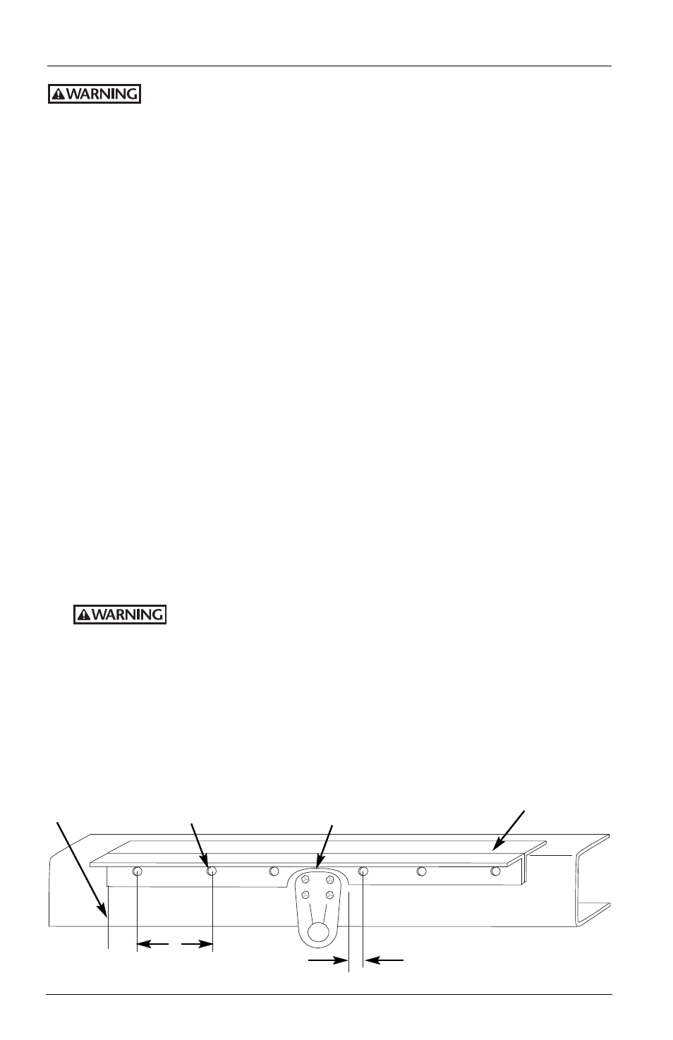
Angle cut out for tractor
frame interference. 1˝
minimum for radius.
1˝ min. from
hole to the end
of the angle.
Holes drilled for
5/8˝ mounting
bolts.
Lift wheel
mounting base.
1˝ – 1
1
⁄
2
˝ mounting required
between 1˝ and 1
1
⁄
2
˝ of
angle cut out.
8˝
Maximum
hole spacing
Figure 1