Installation instructions – SAF-HOLLAND XL-FW488 FW2800 and FW2900 Series Hydraulic Elevating Fifth Wheel User Manual
Page 4
C. Take the marked angles and position them on the tractor frame.
NOTE: The marked angles will no longer be symmetrical. It is critical
to make certain that the angles are notaccidentally reversed.
D. Line up the marks of both angles with the imaginary centerline of the rear
axle/bogie. Use the dimension listed under “Mounting Location (A)” in Chart 1
for the elevating fifth wheel model selected, and offset the angle forward (toward
the cab) by that distance.
NOTE: The offsetting of the angles is necessary to allow for the horizontal (forward)
movement of the wheel when elevating. When the wheel is in its maximum vertical
condition, the pivot point of the wheel will be in line with the imaginary centerline
of the rear axle/bogie and the centerline markings made on the angles in Step 2B,
above (see Figure 2).
3.
Once the proper position of the angles is known, mark the angles in all areas of
interference between the angles and the tractor frame. For example, mark the areas
of the angle needed to be cut out to clear bolts, rivets, spring hangers, etc.
NOTE: A spacer may be
required to obtain
clearance between the
hydraulic cylinder (and
hoses) and the
transmission or cross
members. If a riser is
needed, it may be
necessary to use 5˝x 5˝
angles.
4.
Remove the angles from the tractor frame and machine any interference areas in
accordance with the “Installation: General Recommendations” found on the page 2.
5.
Clamp the mounting angles tightly to the tractor frame. Be certain to check
clearances of cutouts. Drill holes in accordance with the “Installation: General
Recommendations” found on the page 2.
6.
Remove the clamps and fasten the angles, in accordance with the “
General
Information”. In addition, see Figure 5.
7.
Position the fifth wheel
on the mounting angles
with the top plate pivot
on the marked location.
Verify that there are no
interferences and that
the fifth wheel frame
seats flush on the
mounting angles. Tack
weld the fifth wheel to
the mounting angles.
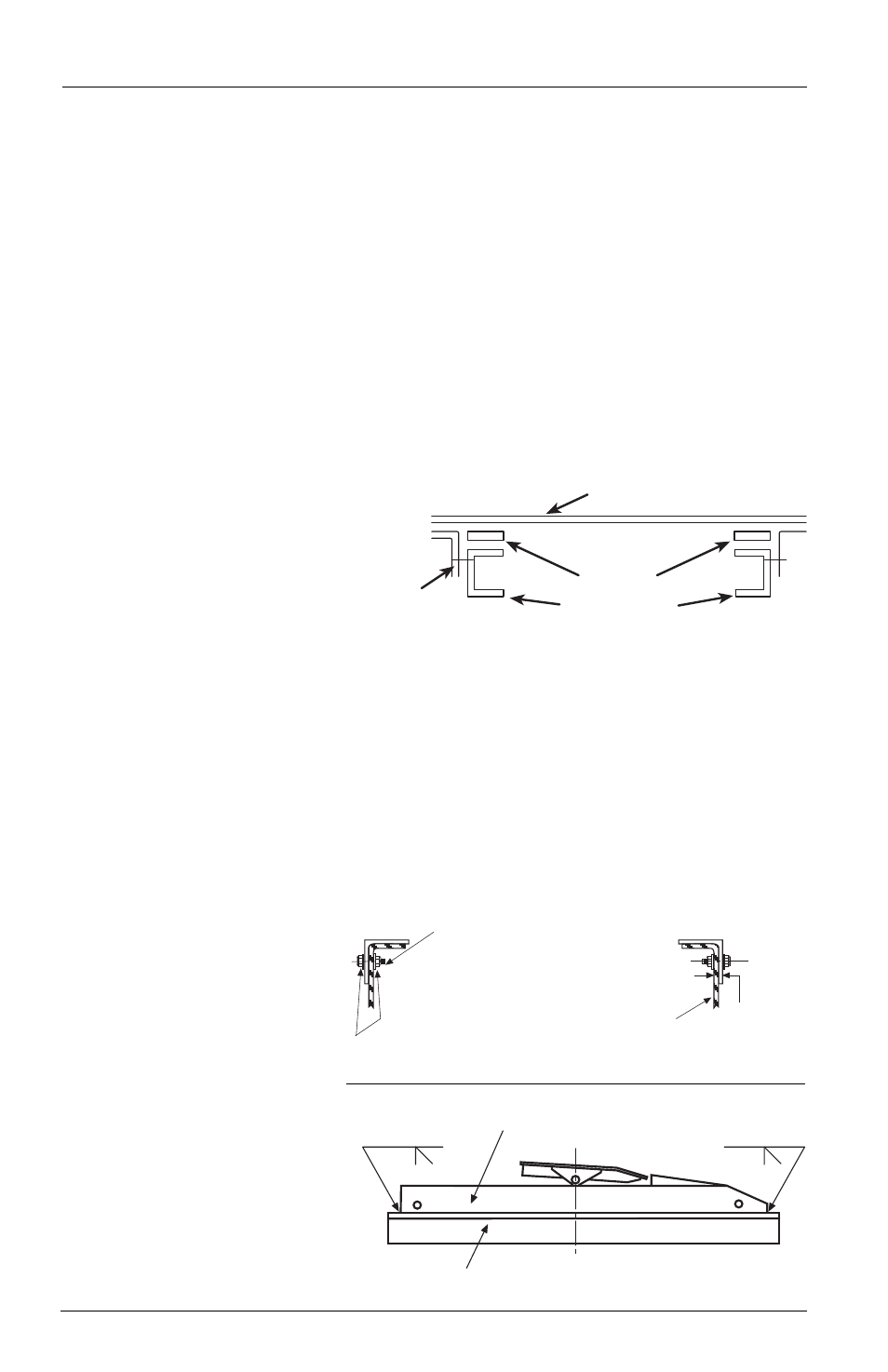
8.
Weld the ends of the
fifth wheel assembly
frame to the top of the
mounting angles with
two 3/8˝ groove welds,
as shown in Figure 6.
4
XL-FW488 Rev A
INSTALLATION INSTRUCTIONS
continued
5˝x 5˝
ANGLE
SPACER
FRAME RAILS
FIFTH WHEEL MOUNTING FRAME
TRUCK
FRAME
RAIL
3/8˝
(9.53mm)
MINIMUM
ANGLE
HARDENED
STEEL WASHERS
The full length of the fifth wheel mounting angle should
seat flush on the truck frame when mounting to prevent
flexing of mounting angle and to give uniform weight
distribution along truck frame rail.
.63” diameter Grade 8 bolts
minimum size.
Tightening torque to bolt
manufacturer charts.
Hardened steel washers or
flanged locknuts. .63”
diameter Grade “C” locknuts.
Figure 4
Figure 5
3/8˝
3/8˝
FIFTH WHEEL MOUNTING FRAME
MOUNTING ANGLE
Figure 6