Installation instructions, Detailed information – SAF-HOLLAND XL-FW488 FW2800 and FW2900 Series Hydraulic Elevating Fifth Wheel User Manual
Page 3
XL-FW488 Rev A
3
INSTALLATION INSTRUCTIONS
continued
6. The bolts attaching the fifth wheel mounting angles to the truck frame require
hardened steel washers under both the bolt and under the locknut, unless flanged
head bolts or flanged head locknuts are employed.
7. A minimum of 5 bolts should be applied to attach each mounting angle to the
tractor frame rail, and the distance between bolts should not exceed 8˝, except
when cutouts are required in the mounting angles (see Figure 1).
8. Whenever a cutout is made on the mounting angle, such as required to bypass
spring hangers, a 1˝ minimum radius should be used and bolts should be placed
within 1-1/2˝, but not closer than 1˝ of the cut, fore and aft (see Figure 1).
9. When initially positioning the fifth wheel for frame holes, the full length of the fifth
wheel mounting angles should seat flush on the top and side surfaces of the truck-
tractor frame rails where channel-type rails are employed. There should not be a
gap over the top of the truck frame rails. The base of the fifth wheel assembly and
of the mounting angle members should seat flush on the top of the frame rail to
prevent flexing and to give uniform weight distribution. It is also recommended to
chamfer or smooth any sharp edges and corners of mounting materials wherever
contact is made with the tractor frame.
10. Review “System Check” found on page 8.
Detailed Information
1. Remove the shipping lugs
from the bottom of the unit.
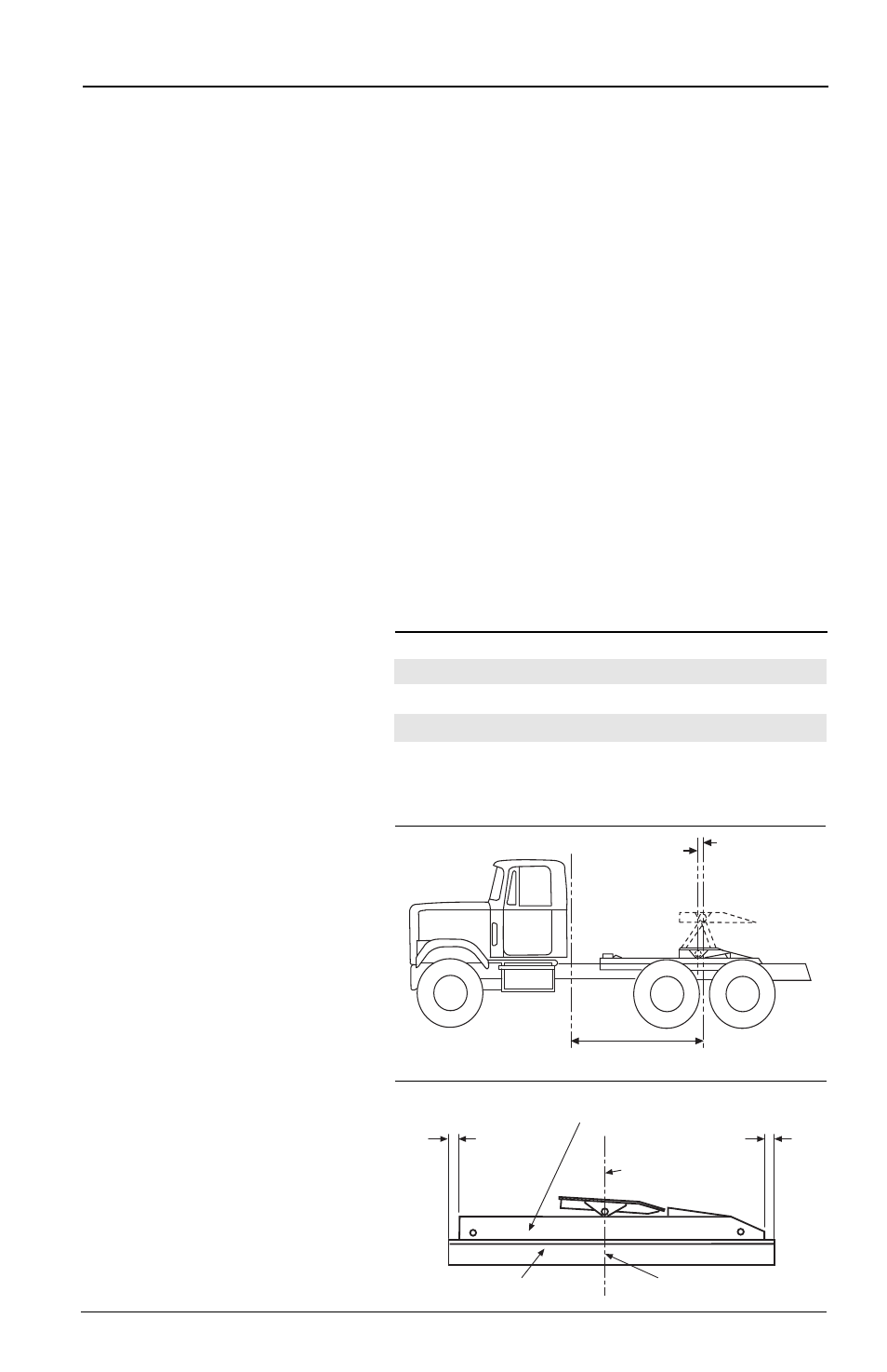
2. Determine the proper fifth
wheel position on the tractor:
A. Verify that the tractor has
sufficient “Cab to Axle”
(C.A.) clearance for the
elevating fifth wheel
model selected, as listed
in
Chart 1 and Figure 2.
B. Locate the pivot point of
the fifth wheel (when it’s
in the down position) on
the given mounting
angles by positioning the
angles approximately 1˝
beyond each end of the
fifth wheel assembly
frame. Once this has been
completed, mark the pivot
point of the fifth wheel on
both angles (see
Figure 3).
Chart 1
Cab to Axle Requirements and Mounting Location
MINIMUM
MOUNTING
MODEL
CAB TO AXLE*
LOCATION (A)
FW2800-X
72˝
10˝
FW2800-5X
77˝
10˝
FW2900-X
60˝
6˝
FW2900-5X
65˝
7˝
APPROX. 1˝
APPROX. 1˝
FIFTH WHEEL MOUNTING FRAME
MOUNTING ANGLE
MARK ANGLES HERE
PIVOT LOCATION
Figure 3
* Based on a 102˝ wide, square corner trailer, with a 36˝
kingpin setting. More or less cab to axle clearance may be
required for other nose configurations, kingpin settings,
refrigeration units, etc.
Figure 2
CENTERLINE
OF THE REAR
AXLE/BOGIE
(A)
FIFTH WHEEL
MOUNTING
LOCATION
CAB TO AXLE
CLEARANCE