Installation instructions – SAF-HOLLAND XL-FW485 FW6000 and FW6200 Series Fifth Wheel User Manual
Page 3
10
XL-FW485 Rev A
XL-FW485 Rev A
3
INSTALLATION INSTRUCTIONS
continued
Tractor Coupler Mounting (Kingpin or Fifth Wheel)
Straight Frame - Without a Body:
In addition to the general installation recommendations listed above, the
following specific recommendations should be followed:
1.
If a folding kingpin is to be installed, see additional procedures under “Tractor Coupler
Mounting (Kingpin or Fifth Wheel) - Non-Straight Frame - With or Without a Body,” on the
next page.
2.
Attach the mounting plate (kingpin or fifth wheel plate) to the frame using a full-
length mounting angle, ASTM A36, 3˝ x 3˝ x 5/16˝ minimum on each side.
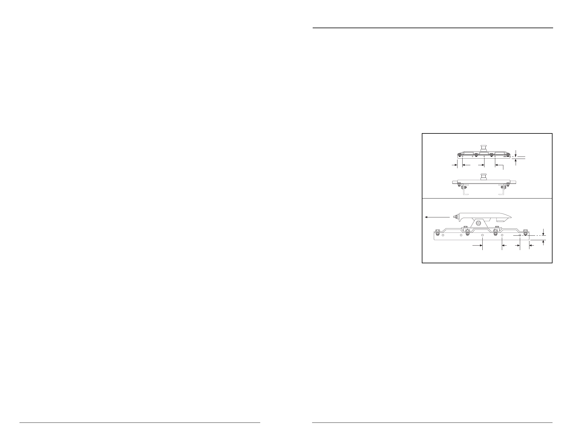
3.
When initially positioning the coupler plate for frame holes, the full length of the
mounting plate should seat flush on the top and side surface of the truck-trailer
frame rails to prevent flexing
and give uniform weight
distribution. There should not
be a gap over the top of the
truck frame rails. It is also
recommended to chamfer or
smooth sharp edges and corners
of mounting materials whenever
contact is made with the truck-
tractor frame. See Figure 1 for
mounting diagrams. A
minimum of four (4) Grade 8˝,
1/2˝ diameter (minimum) bolts
must be used to attach each
mounting angle to the frame.
The distance between the bolts
must not exceed 8˝, except
when cutouts are required in
the mounting angles.
Figure 1
KINGPIN ATTACHMENT
FIFTH WHEEL ATTACHMENT
2˝
2˝
1˝ MIN.
1˝ MIN.
8˝ MIN.
8˝ MAX.
FRONT OF
VEHICLE