Maintenance procedures, Installation instructions, As-needed lubrication – SAF-HOLLAND XL-FW485 FW6000 and FW6200 Series Fifth Wheel User Manual
Page 8: Periodic inspections and adjustments, Inspection — general
8
XL-FW485 Rev A
MAINTENANCE PROCEDURES
As-Needed Lubrication
1.
Keep a water-resistant lithium-base grease applied to the trailer contact surface of
the fifth wheel plate.
2.
Lubricate all moving parts with a light, rust-resistant oil.
3.
Apply a light grease through the grease zerks at the pivot points and the cam.
Periodic Inspections and Adjustments
NOTE: All of the following must be performed every 30,000 miles or 3 months, whichever
comes first. Perform the inspections after steam cleaning to assure a good inspection.
Inspection — General
1.
Inspect the fifth wheel and the kingpin mountings. Check torque and replace any
missing or damaged bolts. Check for broken or distorted components and repair or
replace as needed.
2.
Inspect the fifth wheel assembly for bent, worn or broken parts. Replace with
HOLLAND parts only.
Fifth Wheel Locking Mechanism Inspection and Adjustment
1.
Check the operation of the fifth wheel locking mechanism using a HOLLAND
TF-TLN-1000 (2˝ kingpin) or TF-TLN-1500 (31/2˝ kingpin) Lock Tester. Inspect for
proper locking as described in the “Operating Instructions” in this manual.
Do not use any fifth wheel which does not operate properly.
2.
Check adjustment of the fifth wheel locks and adjust as required. The lock adjusting
nut is located at the front edge of the fifth wheel (see Figure 6A on page X). With
the wheel locked around the lock tester, tighten or loosen the nut until the rubber
washer seats snugly against the fifth wheel (but can still be turned by hand).
Viewed from the adjusting nut, a counter-clockwise rotation of the nut will allow
the yoke (see Figure 6A) to move in and tighten the locks on the kingpin. A
clockwise rotation will pull the yoke out and loosen the locks. Remove and reinsert
the lock tester to verify proper adjustment and coupling.
3.
Relubricate by applying a light, rust-resistant oil to all moving parts.
1. All maintenance must be performed by a qualified person using
proper tools and safe procedures.
2. All maintenance must be performed while the tractor is uncoupled
from the trailer.
XL-FW485 Rev A
5
INSTALLATION INSTRUCTIONS
continued
2.
Tab Mount - Acceptable
In addition to the general installation recommendations listed on the previous page,
the following specific recommendations must be followed:
A. If a full-length mounting angle is impractical, an angle TAB mount, as shown in
Figure 3, is acceptable. The angle TABS should be 3˝ x 3˝ x 3/8˝ x 3˝ long
minimum, using an ASTM A36 steel. A minimum of 4 TABS per side are required.
B. The TABS must be attached to the tractor frame using 1/2" diameter (minimum)
Grade 8 fasteners.
C. Proper length tube spacers (3/4˝ I.D. x 1 1/2˝ O.D. recommended) must be used
to shim the distance between the TAB angles and the coupler mounting plate.
Tractor Coupler Mounting – Kingpin or Fifth Wheel Mount:
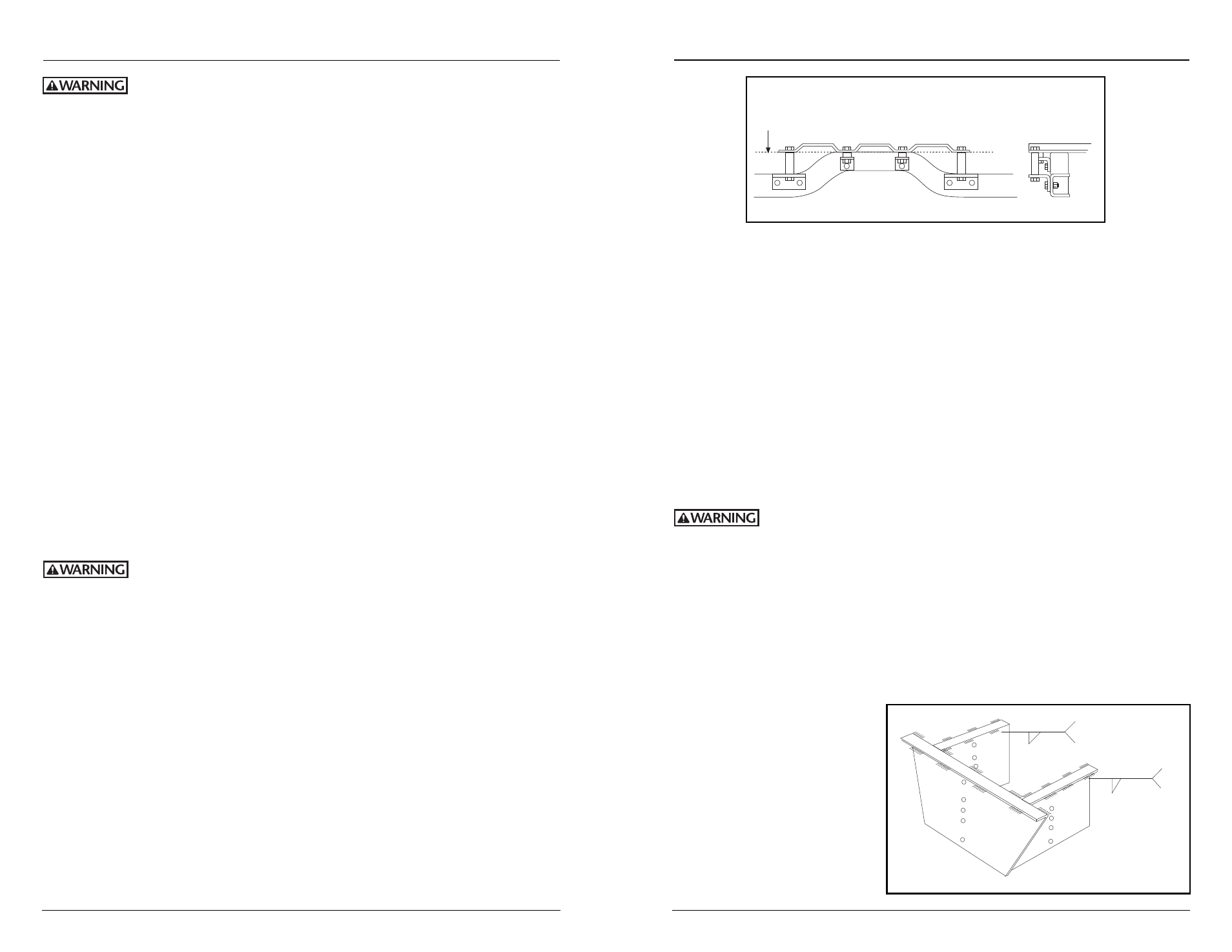
The kingpin mounting box is designed to be attached to the trailer frame by welding. It
is imperative, therefore, that the attachment is substantial enough to develop the full
strength of the hitch.
When welding, use a procedure which assures a sound, good quality
weld and which protects the operator and others. Over-welding may
cause distortion and damage and underwelding may not develop sufficient strength. A
low hydrogen process and AWS E70XX filler metal are recommended. Take precautions
to insure that the trailer electrical system is not damaged by the welding.
1.
Weld as shown in Figure 5, making
1
/
4
˝ fillet welds on the inside and
3
/
16
˝ fillet welds
on the outside, with skip welds 2˝ long on approximately 6" centers (weld 2˝, skip
4˝). Weld inside opposite skips on the outside.
2.
Install and adjust inner box to required height. Use the six (6) Grade 5 fasteners
provided (2 each hole series) and tighten to 65 ft. - lbs.
3.
When installing a fifth wheel
on a trailer mounting box, be
certain that the open end of
the fifth wheel faces the front
of the trailer (see
Figure 7A).
1/4
2 – 6
TYP.
3/16
2 – 6
TYP.
Figure 5
Figure 3
ACCEPTABLE MOUNTING METHOD
BODY FLOOR