Coupling procedures, Uncoupling procedure, Operating instructions – SAF-HOLLAND XL-FW485 FW6000 and FW6200 Series Fifth Wheel User Manual
Page 7
Coupling Procedures
continued
CHECK 3
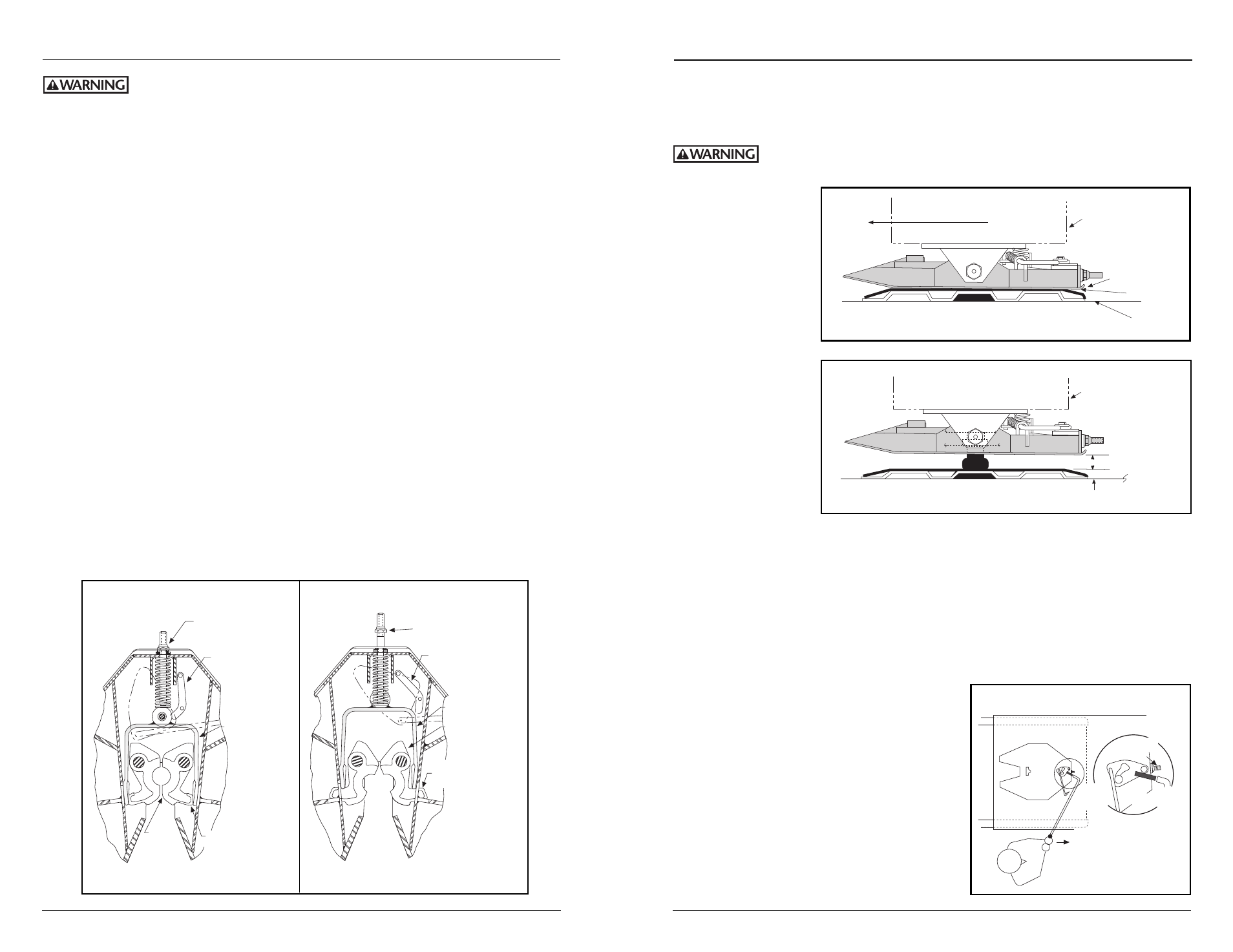
The fifth wheel must be flush with the kingpin plate (see Figure 7A).
A direct visual inspection is required to assure proper coupling. Do not
use any fifth wheel which does not operate properly.
9. Connect the
power/brake
line(s).
10. If the trailer is
equipped with
electric brakes,
connect the
breakaway switch
line.
11. Retract the
landing gears,
raise the tailgate,
pick up the wheel
chocks.
FRONT OF VEHICLE
CORRECT ENGAGEMENT
Mounting Box
for Fifth Wheel
to Trailer
CHECK NO. 3
No Space
between Fifth
Wheel and
Kingpin Plate
No Space
Bed of
Truck
Space
SPACE
INCORRECT ENGAGEMENT
Mounting Box
for Fifth Wheel
to Trailer
Bed of Truck
Figure 7A
Figure 7B
Uncoupling Procedure
1.
Set trailer brakes and chock trailer wheels.
2.
Lower the landing gear; when the foot pad contacts the ground, crank two or three
additional turns to reduce the vertical load on the fifth wheel. Do not raise the fifth
wheel off the kingpin plate.
3.
If the truck/tractor is equipped with a body, lower the tailgate.
4.
Disconnect the power/brake line and, if the
trailer is equipped with electric brakes,
unhook the breakaway switch line. Do not
disconnect at the switch.
5.
Open the fifth wheel locks by . . .
A.
pulling the release handle or . . .
B.
from the driver’s side, slide a pipe
release handle over the solid stud,
located next to the adjusting bolt and
push toward the rear of the vehicle
(see
Figure 8). Remove and store the
handle.
6.
Drive away from the trailer slowly.
7.
Raise the tailgate if so equipped.
XL-FW485 Rev A
7
OPERATING INSTRUCTIONS
continued
6
XL-FW485 Rev A
OPERATING INSTRUCTIONS
Relative to tractor/trailer operations, there are other checks, inspections,
and procedures not listed here, which are necessary, prudent, and/or
required by law. The following is in addition to these, and pertains to the fifth wheel only.
Perform these procedures with the area clear of obstacles and other personnel.
Coupling Procedures
1. Check out the equipment before coupling.
A.
Make sure that the fifth wheel is properly lubricated, that the locks are open,
and that the ramps are tilted in the proper position.
B.
Make sure the mounting of the fifth wheel is in good condition and is tight.
C.
Make sure the power/brake line and breakaway line (if the trailer is equipped
with electric brakes) and clear of the coupling area.
2. If the tractor is equipped with a body, lower the tailgate.
3. Back up close to the trailer, centering the kingpin on the crotch of the fifth wheel.
STOP!
4. Chock the trailer wheels.
5. Check the trailer height for coupling. The fifth wheel should just touch the kingpin
plate; adjust the landing gears as necessary.
6. Back
slowly under the trailer, keeping the kingpin centered in the crotch of the fifth
wheel until the fifth wheel locks firmly on the kingpin. Pull forward to check the
completeness of the coupling as an initial check.
7. Visually check to see that the kingpin is in the fifth wheel lock.
8. Visually check that the locks are properly locked on the kingpin by the following (3) checks.
CHECK 1
The adjustment nut must be seated against the fifth wheel (see Figure 6A).
CHECK 2
The secondary lock must be behind the yoke (see Figure 6A).
LOCKS SHOWN IN CLOSED POSITION
CHECK NO. 1
Nut Seated on
Fifth Wheel
CHECK NO. 2
Secondary Lock
Behind Yoke
Yoke
Yoke Flush with
Ends of Locks
Locks
LOCKS SHOWN IN OPEN POSITION
NOTE:
Nut away from
Fifth Wheel
NOTE:
Secondary Lock
away from Yoke
Yoke
NOTE: Locks
Extend through
Window to Open
Locks
Figure 6A
Figure 6B
SOLID
STUD
YES!
PIPE
RELEASE
HANDLE
RELEASE
HANDLE
NO!
ADJUSTING
BOLT & NUT
NO!
PUSH
TOWARD
TRAILER
Figure 8