Installation instructions, Sliding fifth wheel installation - ils slider, Outboard angle mounting – SAF-HOLLAND XL-FW484 FW33 and XA-331 LowLube Series Fifth Wheels User Manual
Page 7
INSTALLATION INSTRUCTIONS
continued
XL-FW484 Rev E SAF-HOLLAND, Inc.
7
Sliding Fifth Wheel Installation - ILS Slider
continued
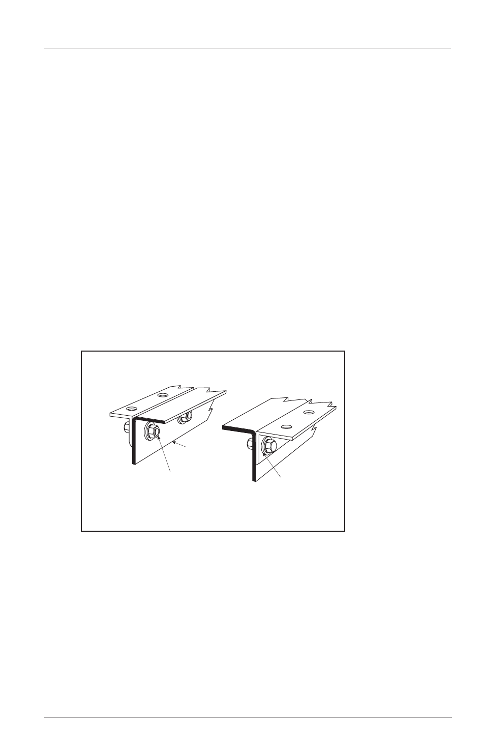
Outboard Angle Mounting
(See Figure 5):
1. If angles are not installed, see “Installation: General Recommendations,” on page 3,
for thickness and material. Use 3˝ minimum horizontal and 3-1/2˝ minimum vertical
leg size. Longer horizontal legs may be required with narrow frame widths. The
recommended length of each mounting angle is the same length as the slide base
mounting plate.
2. In addition to the information given in “Installation: General Recommendations,”
on page 3, follow the recommendations in FIGURE 5. The following sequence is
suggested:
A. Securely position the mounting angles to the tractor frame and attach as shown
in FIGURE 5. Follow the bolting recommendations as shown in FIGURE 4. Angles
must be flush with the top of the truck frame.
B. Locate the slide base and center left to right and front to rear on the mounting
angles. Clamp in place and drill 21/32˝ diameter holes using the mounting plate
as a template if holes are not provided in the angle.
C. Align holes in the slide plate with outboard angle mounting holes and bolt
using Grade 8 fasteners, hardened steel washers and Grade C locknuts, properly
tightened, (see FIGURE 5). Use all mounting holes on the fifth wheel.
TRUCK FRAME RAIL
HARDENED STEEL
WASHERS
5/8˝ diameter Grade 8 bolts minimum size,
tightening torque to bolt manufacturer charts.
Hardened steel washers or flanged locknuts.
5/8˝ diameter Grade “C” locknuts.
The full length of the fifth wheel mounting angle should seat
flush on the truck frame to prevent flexing of mounting angle
and to give uniform weight distribution along truck frame rail.
FIGURE 5