Installation instructions, Inspection and lubrication prior to use – SAF-HOLLAND XL-FW484 FW33 and XA-331 LowLube Series Fifth Wheels User Manual
Page 8
8
SAF-HOLLAND, Inc. XL-FW484 Rev E
INSTALLATION INSTRUCTIONS
continued
Attachment of Air-Activated Slide Release – If Required
1. Mount the cab control valve in accordance with the instructions provided. It should
be readily accessible to the driver, but protected to prevent accidental activation.
2. Attach an air line, using appropriate fittings to the “air” or “in” port of the valve.
Use an air source recommended by the tractor manufacturer. Use fittings and lines
of suitable pressure rating.
3. Make sure that the air supply to the fifth wheel and slide base is turned off.
4. Remove any masking that may be present on the bulkhead and union fittings.
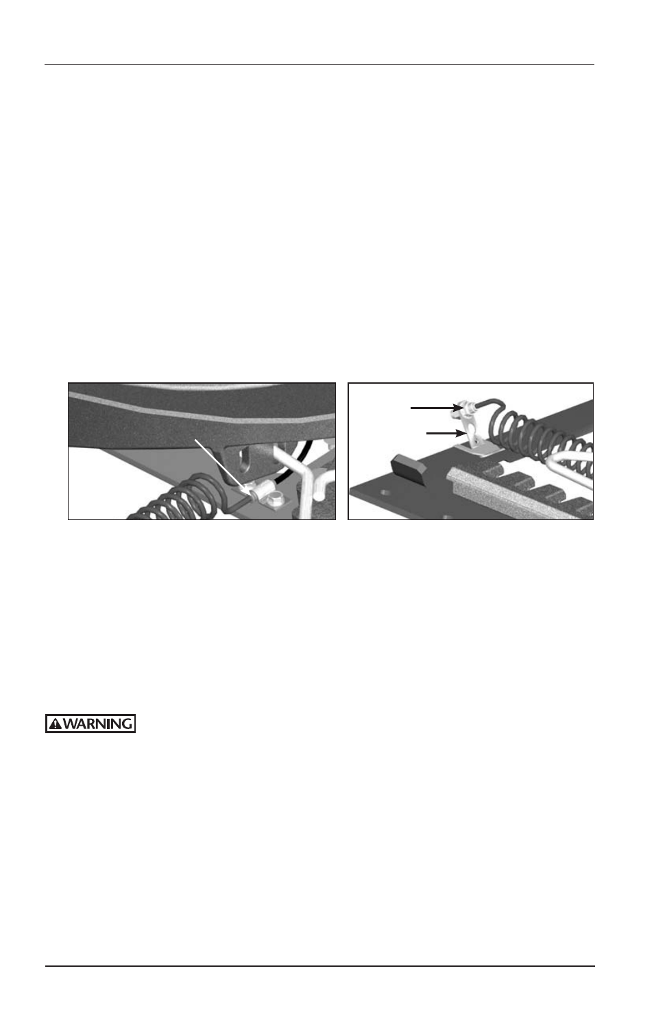
5. Connect the coiled air line by pushing it into the union fitting as shown in
FIGURE 6.
6. Connect the other end of the coiled air line by pushing it into the bulkhead fitting
on the standoff as shown in FIGURE 7.
NOTE: If there are any undesired line interferences, there is an optional hole in the
standoff that the bulkhead fitting can be mounted in.
7. Turn on the air supply to the fifth wheel and slide base; check for proper function.
Inspection and Lubrication Prior to Use
1. Review the installation. Be sure all nuts and bolts are in place and properly
tightened. Be sure all necessary steps were properly followed and that all
components removed to facilitate installation are reinstalled.
2. Check the fifth wheel locking mechanism with a Holland TF-TLN-5001 (2˝) or
TF-TLN-1500 (3-1/2˝) Lock Tester. Examine for proper locking as described in the
“Operating Instructions” of this manual. This must be done to assure that the
mechanism has not been damaged by shipment, handling, or storage.
Failure to properly install, operate, or maintain this fifth wheel may
result in tractor and trailer separation which, if not avoided, could
result in death or serious injury.
3. Apply grease to the bearing surface of the support bracket through the grease
fittings on the side or front of the fifth wheel pockets. The top plate must
be lifted up slightly to ensure proper application of grease. (NOTE: This is not
required on Holland LowLube and NoLube top plates.)
4. Apply a generous coating of grease to the top of the fifth wheel plate, where it
will contact the trailer plate. (NOTE: This is not required on Holland LowLube and
NoLube top plates.)
5. Apply a generous coating of grease to the front lock and lock jaws.
COILED
AIR LINE
UNION FITTING
BULKHEAD
FITTING
STANDOFF
FIGURE 6
FIGURE 7