Fig. 1 1.0 mounting, 0 wiring, Wiring diagram – Whelen 295SLSA6 User Manual
Page 2: Siren amplifier, Fig. 2, Page 2, 1 bail strap mount, 2 console mount, 3 microphone clip
Page 2
CUT
WIRE
HORN
RELAY
+12V
TO
HORN
BUTT
ON
WIRING
DIAGRAM
10 GREY
11 WHITE
12 YELLOW
100W
SPEAKER
#2
TO
2-
W
AY
RADIO SPEAKER
3-POS.
INPUT
CONN.
SIREN
INPUT
CONNECT
OR
100W
SPEAKER
#1
VEHICLE HORN
8 ORANGE
7 BROWN
3 BLUE
6 BLUE
9 VIOLET
AUX OUTPUT NO
AUX OUTPUT NC
AUX INPUT
AUX OUTPUT NO
AUX OUTPUT NC
AUX INPUT
15 AMP OUTPUT
15 AMP OUTPUT
15 AMP OUTPUT
15 AMP OUTPUT
5 BLACK
2 BLACK
4 RED
1 RED
20 AMP FUSE
2 WHT/ORG
3 WHT/GRN
Siren interruption
Ground to activate.
CHASSIS
GROUND
Backlight
Control Voltage (+12 VDC)
“Siren In Use" Icon
Input on Video Camera
Auxilliary Enable
(Optional)
1 WHT/YEL
Siren
Amplifier
BATTERY
Fig. 2
RED
RED
Both RED Wires: 60 AMP FUSE
20 AMP OUTPUT
20 AMP OUTPUT
20 AMP OUTPUT
16.5
12.5
10
8
7
26
19.5
15.5
13
11
41.5
31
25
20.5
17.5
66
49.5
39.5
33
28
104
78.5
63
52.5
45
6
10 15.5 24.5 39
30
40
50
60
70
10
8
6
4
2
80
24.5 39 62 98.5 157
20
10.5
7.5
6
5
4.5
4
12
15.5
Wire Gauge / AWG
TABLE 1
Current
Draw
/AMPS
Distance
is
shown
in
feet.
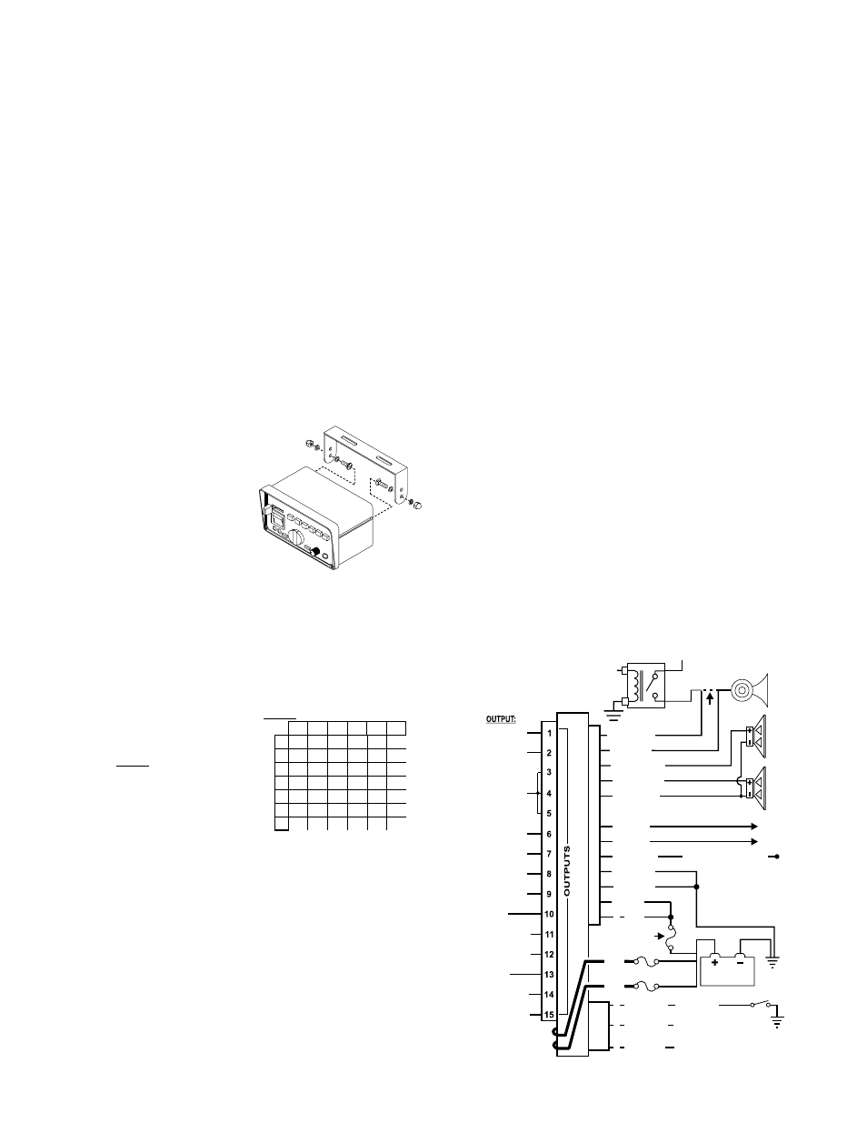
Fig. 1
1.0 Mounting:
This siren is designed to be mounted directly onto the dash or other surface through
the use of a bail strap mounting bracket. The unit may also be mounted into your
vehicle’s console (if so equipped).
WARNING: Regardless of the style selected, be sure to observe the air bag
warning on the cover of this manual.
WARNING: Mounting this unit will require drilling. It is absolutely necessary to
make sure that no other vehicle components could be damaged in the process.
Check both sides of the mounting surface before starting. If damage is likely,
select a different location.
1.1 Bail Strap Mount:
1.
Position bail strap in selected mounting location
and drill mounting holes, then secure the
bail strap to the vehicle.
2.
Secure the siren to the bail strap as
shown. Tighten the acorn nuts firmly.
1.2 Console Mount:
Console manufacturers offer mounting kits that
include all the necessary hardware and brackets
required to mount this unit into their console. The console
mount brackets are secured onto the unit in the same way.
Please refer to the manual included with your console.
1.3 Microphone Clip:
A microphone clip is included with this product.
WARNING: Refer to the Air Bag Warning before installing this clip.
2.0 Wiring:
2.1 Siren Input Connector - RED: Power - BLACK: Ground
WARNING: All customer supplied wires
that connect to the positive terminal of
the battery must be sized to supply at
least 125% of the maximum operating
current and FUSED at the battery to
carry that load. DO NOT USE CIRCUIT
BREAKERS WITH THIS PRODUCT!
1.
Splice the 2 RED (Power) wires
together, then extend this single RED
wire toward the vehicle battery. Splice
the 2 BLACK (Ground) wires together and extend this single BLACK wire
toward the vehicle battery. To pass the RED and BLACK wires through, you
may have to drill a hole in the firewall. Insert a grommet to protect the wires.
2.
Route the RED and BLACK wires along the factory harness towards the
battery and install a fuse block (user supplied) on the end of the RED wire.
Remove fuse from fuse block before connecting any wires to battery.
3.
Connect fuse block wire to POSITIVE terminal on battery. There must not be
more than 2 feet of wire between fuse block and battery. The wire between the
4.
fuse and battery is “unprotected”, do not allow it to chafe and short to ground.
Connect the BLACK wire to the factory chassis ground.
ORANGE, YELLOW & BROWN - Speaker Wires
1.
Route the ORANGE, YELLOW and BROWN wires toward vehicle siren
speakers, along factory wire harness and through firewall at the same point as
the RED and BLACK wires.
2.
Connect the YELLOW wire to the POSITIVE terminal on SPEAKER #1 and the
ORANGE wire to the POSITIVE terminal on SPEAKER #2. NOTE: For single
speaker installations use the YELLOW wire and cap the ORANGE wire.
3.
Connect BROWN wire to NEGATIVE connection on speakers #1 & 2.
WHITE & GREY - Horn Relay Wires:
1.
Route WHITE and GREY wires along factory wire harness and through firewall
at the same point as the RED and BLACK wires.
2.
Route WHITE and GREY wires to vehicle’s horn relay. If possible, follow the
factory wire harness to this relay.
3.
Locate the wire that connects the vehicle horn to the horn relay and cut it.
4.
Connect the WHITE wire to the wire coming from the horn relay.
5.
Connect the GREY wire to the wire coming from the horn.
Two BLUE wires - Radio Rebroadcast (optional):
The two remaining BLUE wires are used to connect your two-way radio’s
external speaker for radio rebroadcast (optional connection).
Note: If your remote speaker is amplified (speaker has a power amp circuit),
radio rebroadcast will not work and should not be used.
1.
Locate the 2 wires that connect the external speaker to the 2-way radio, cut
one of them and splice one of the BLUE wires into this circuit.
2.
Cut the remaining speaker wire and splice the other BLUE wire into this circuit.
VIOLET - Siren Interruption:
Grounding the VIOLET wire will deactivate the siren. The siren can be programmed
to reactivate the tones by 2 different methods (See section 6.8) This wire doesn’t
affect HORN or MAN push button operations.
• Programmable Power Distribution Switches
• Power to drive two, 100-Watt Speakers
• Scan-Lock™ Power Distribution & Siren Tone
Programing
• Siren Interruption Control
• High and Low Voltage Shutdown
• Program the Siren Tone and the Override Tone of
any Rotary switch position
• Enabling or Disabling Auxiliary Siren from the
power distribution control switches
• Power distribution control switch type
selection (push on push off, momentary,
flashing, timed output)
• Auxiliary Input Control
• Hands-Free Operation
• Horn Ring Transfer
• Simulated mechanical Siren Tones
• Speaker Diagnostics
• “Siren In Use” Output
• LED Backlighting
• Harmonically-rich, composite Airhorn Tones
• Title 13-Compliant Profiles
• Non-destructive Short Circuit Protection
• Meets Class A Sound Requirements
• External Back-light Control
• Radio Repeat
• Copy one units configuration to another unit
• Easy reset to default settings
• Power Distribution fuses included
Congratulations on selecting the 295SLS-Series Siren. This series offers a unique collection of features designed to allow the user to
customize the operation of this siren to suit their individual needs. Features include: