0 terminal operation, Fig. 4, 0 rotary switch operations – Whelen 295SLSA6 User Manual
Page 4: 1 terminal specifications
Page 4
10
11
12
13
14
15
AUX CIRCUIT
POWER IN
F8A
V
BA
T
RED
10
AW
G
RELA
Y
8
N/C
F8
F9A
F9
15 AMP
AUX CIRCUIT
POWER IN
NO
15 AMP
N/C
NO
Fig. 4
RELA
Y
9
4.0 Rotary Switch Operations:
This section will outline the operation of the siren in the factory default
configuration. Refer to Section 6.3 for information on how to customize the
operation of this siren.
4.1
RAD - Radio Repeat:
When the rotary knob is in the RAD position, any
signal that is received by the vehicle’s two-way radio will be simultaneously
broadcast over the vehicle’s loudspeaker (the unit must be connected to the two-way
radio as outlined in this manual).
With the Rotary Switch in this Position:
•
Activating the HORN button will produce the AIRHORN tone until released.
•
Pressing the MAN button will start SI TEST® as described in Section 3.6.
•
Activating the HORN RING input will produce the AIRHORN tone until the
HORN RING switch is released.
•
Activating the AUX ENABLE input has no effect.
4.2 MAN 1 - Manual Siren #1:
When the rotary switch is in this position the
siren is in a standby state where no tones have been activated, but is waiting for
another action to be taken by the operator.
With the Rotary Switch in this Position:
•
Activating the HORN button will produce the AIRHORN tone until released.
•
Pressing the MAN button will produce the AIRHORN tone until the MAN switch
is released.
•
Activating the HORN RING input will produce the AIRHORN tone until the
HORN RING input is released.
•
Activating the AUX ENABLE input will produce a repeating WAIL tone.
4.3 MAN 2 - Manual Siren #2:
When the rotary switch is in this position the
siren is in a standby state. No tones will be activated until another action is taken by
the operator.
With the Rotary Switch in this Position:
•
Activating the HORN button will produce the AIRHORN tone until released.
•
Pressing the MAN switch will produce a WAIL tone. This tone will ramp up to
peak frequency and stop when the MAN switch is released.
•
Activating the HORN RING input will produce a WAIL tone. This tone will ramp
up to peak frequency and stop when the HORN RING input is released.
•
Activating AUX ENABLE will produce a repeating WAIL tone.
4.4 HF - Hands-Free Operation -
When the rotary knob is in the HF
position, the siren functions are placed in a stand-by mode. Siren tones are activated
by a single “tap” on the MAN button or on the vehicle’s steering wheel horn ring (if the
vehicle’s horn has been wired to the HORN RING input). The first tap produces a
“Wail” tone (a steady rise and fall tone). A second tap produces a “Yelp” tone (a fast
rise and fall tone). A third tap produces a “Piercer™” tone (an extremely fast rise and
fall tone). The next tap returns the siren to a Wail tone and the cycle repeats itself.
Two quick successive taps will stop the siren.
With the Rotary Switch in this Position:
•
Activating the HORN button will produce the AIRHORN tone until released.
•
Pressing the MAN button will produce the HF cycle.
•
Activating the HORN RING input will produce the HF cycle.
•
Activating the AUX ENABLE input will start the HF cycle. Releasing the AUX
ENABLE will stop the cycle.
4.5 T1 - Tone #1:
When the rotary knob is in the T1 position, a steady, rise and
fall tone (WAIL) is produced.
With the Rotary Switch in this Position:
•
Activating the HORN button will produce the AIRHORN tone until released.
•
Pressing the MAN button will change the siren tone to a yelp pattern (a fast rise
and fall tone). Pressing the MAN button a second time returns it back to WAIL.
•
Activating the HORN RING input will change the siren tone to YELP. Activate
the HORN RING input again to return to WAIL.
•
Activating the AUX ENABLE input has no effect.
4.6 T2 - Tone #2:
When the rotary knob is in the T2 position, a fast, rise and fall
tone (YELP) is produced.
With the Rotary Switch in this Position:
•
Activating the HORN button will produce the AIRHORN tone until released.
•
Pressing the MAN button will produce the PIERCER tone. Pressing the MAN
switch a second time returns it back to YELP.
•
Activating the HORN RING input will produce the AIRHORN tone until the
HORN RING input is released.
•
Activating the AUX ENABLE input has no effect.
4.8 T3 - Tone #3:
When the rotary knob is in the T3 position, an extremely fast,
rise and fall tone is produced.
With the Rotary Switch in this Position:
•
Activating the HORN button will produce the AIRHORN tone until released.
•
Pressing the MAN button will result in the AIRHORN tone until released.
•
Pressing the HORN RING input will result in the AIRHORN tone until the
HORN RING input is released.
•
Activating the AUX ENABLE will have no effect.
5.0 Terminal Operation
5.1 Terminal Specifications
This siren contains 15 screw terminals located in the upper rear panel of the housing.
They are designed to activate components that do not exceed specific current draw.
NOTE: It is important that any components connected to these terminals
do not exceed the maximum current rating for that terminal.
Warning! Total power distribution current is not to exceed 80 AMPS.
Terminal Max. Load
Fuse
1 . . . . . . . 20 Amps . . . . . . . . . . . . . . . . . . . . . . . . . . . . . . . . . . . . . . . . . . . . F1
2 . . . . . . . 20 Amps . . . . . . . . . . . . . . . . . . . . . . . . . . . . . . . . . . . . . . . . . . . . F2
3, 4 & 5. . 20 Amps Total: These terminals can’t be activated individually . . F3
6 . . . . . . . 15 Amps . . . . . . . . . . . . . . . . . . . . . . . . . . . . . . . . . . . . . . . . . . . . F4
7 . . . . . . . 15 Amps . . . . . . . . . . . . . . . . . . . . . . . . . . . . . . . . . . . . . . . . . . . . F5
8 . . . . . . . 15 Amps . . . . . . . . . . . . . . . . . . . . . . . . . . . . . . . . . . . . . . . . . . . . F6
9 . . . . . . . 15 Amps . . . . . . . . . . . . . . . . . . . . . . . . . . . . . . . . . . . . . . . . . . . . F7
11 . . . . . . 15 Amps
12 . . . . . . 15 Amps . . . . . . . . . . . . . . . . . . . . . . . . . . . . . . . . . . . . . . . . F8/F8A
14 . . . . . . 15 Amps
15 . . . . . . 15 Amps . . . . . . . . . . . . . . . . . . . . . . . . . . . . . . . . . . . . . . . . F9/F9A
(Terminals 11 & 14 are always on unless otherwise noted)
In the factory default configuration terminal outputs of the siren are:
Slide Switch Positions:
Push-Button Switches:
0 = Terminals OFF
4 = Terminal #6 ON
1 = Terminal #1 ON
5 = Terminal #7 ON
2 = Terminals #1 & 2 ON
6 = Terminal #8 ON
3 = Terminals #1, 2, 3, 4 & 5 ON
7 = Terminal #9 ON
8 = Terminal #12 ON / Terminal #11 OFF
9 = Terminal #15 ON / Terminal #14 OFF
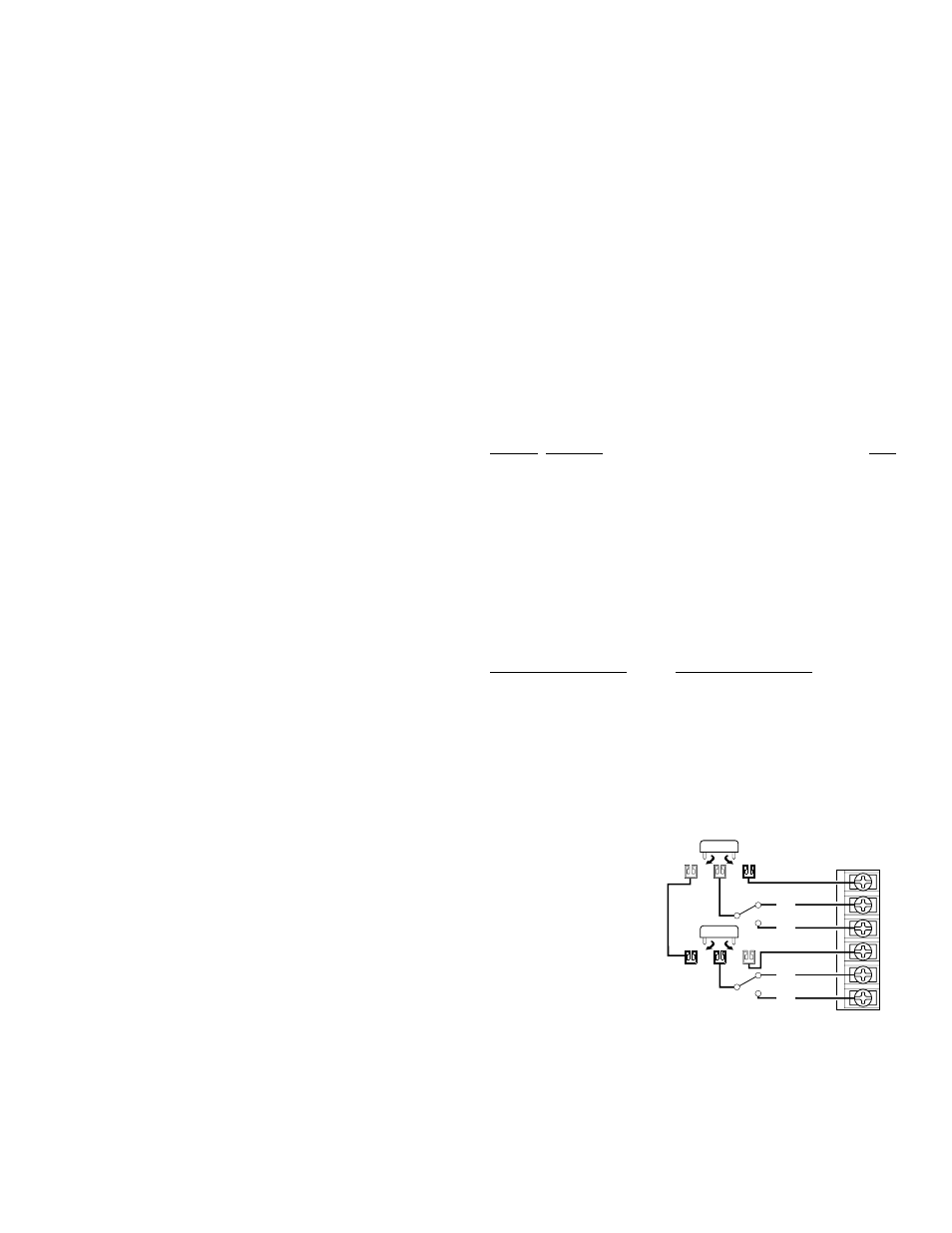
5.2 Custom Fuse Configurations: Push-Buttons 5 & 6
Functionality
(Fuse Locations / Section 7.0)
Terminals #10 & 13 do not
function as output terminals and
are not used in the default
configuration. By changing the
positions of specific fuses, these
terminals can be configured to
control auxiliary circuits. These
auxiliary circuits can not exceed
15 amps each.
Moving Fuse #8 from its default
position (F8) to its optional
position (F8A) allows push-
button 5 to control an auxiliary circuit. Connect Power In from the aux. circuit to
Terminal #10 and Load Out to Terminal #11 or 12. Push-button 5 will now open and
close this circuit.
Moving Fuse #9 from its default position (F9) to its optional position (F9A) allows
push-button 6 to control an auxiliary circuit. Connect Power In from the aux. circuit to
Terminal #13 and Load Out to Terminal #14 or 15. Push-button 6 will now open and
close this circuit.