Fig. 6, 4 copying a units configuration, 5 title 13 operation – Whelen 295SLSA6 User Manual
Page 6: 6 power switch configuration, 7 re-setting factory defaults, 8 siren interruption configuration, 0 accessing the circuit board, 1 specifications
Page 6
Pause Mode
Cancel Mode
1
On
Off
2
Off
On
Speaker LEDs
Interruption Mode
6.4 Copying a Units Configuration:
If more than one siren needs to be configured to operate in the same manor, it is not
necessary to configure each unit separately. Once one unit has been configured to
operate as desired, it can now be used as the “primary” unit and its configuration can
be copied to another unit that is set up as a “secondary” unit.
To Copy a Configuration to a Second Unit:
1.
Connect both units to a common power source (V BAT & Ground). Leave
all other wiring not connected.
2.
Put the PRIMARY unit into "transmit" mode.
•
Turn the POWER switch off.
•
Place the SLIDE SWITCH in the off position.
•
Place the rotary switch into the MAN2 position.
•
Hold Scan-Lock™ switch in while turning power switch on.
To confirm entry to this mode the momentary switch 6 light will turn on.
3.
Put the SECONDARY unit into "receive" mode:
•
Turn the POWER switch off.
•
Place the SLIDE SWITCH in the off position.
•
Place the rotary switch into the MAN1 position.
•
Hold Scan-Lock switch in while turning power switch on.
To confirm entry to this mode the momentary switch 1 light will go on.
4.
Connect the WHITE/ORANGE wire from the
PRIMARY
unit to the WHITE
wire of the
SECONDARY
unit. The Speaker #1 indicator will
begin to flash on the
SECONDARY
unit to indicate that
communications have been established.
5.
Press
and release the MAN switch on the
PRIMARY
unit to start a
transfer. When the indicator for Speaker #2 begins to flash on the
SECONDARY unit
, the transfer is complete.
6.
When done programming, turn power off, then on to activate changes.
6.5 Title 13 Operation:
Airhorn will not override primary tones. To put the siren into Title 13
operation mode:
1.
Turn the POWER switch OFF.
2.
Place the SLIDE SWITCH in the OFF position.
3.
Place the ROTARY SWITCH into the MAN1 position.
4.
Hold Scan-Lock™ and HORN switch in while turning power on. Momentary
switch 4 light will turn on when a set of Title 13 compliant tones have been
programmed for use.
Turn power off, then on to activate changes.
6.6 Power Switch Configuration:
The power distribution switch’s can be configured to operate inde-
pendently of the main power switch (default) or operate only with the
main power switch in the on position.:
To make the power distribution switch’s operate with the main power switch.
1.
Turn the power switch off.
2.
Place the SLIDE SWITCH in the OFF position and the ROTARY switch in the
RAD position.
3.
Hold Scan-lock™ and HORN switch’s in while turning POWER switch on. To
make the power distribution switch’s operate independently of the main power
switch, restore factory defaults (See Section 6.7).
When the power switch is configured the momentary switch 5 light will go on.
Turn power off, then on to activate changes.
6.7 Re-Setting Factory Defaults:
To restore siren tones to the factory defaults:
1.
Turn the POWER switch OFF.
2.
Place the SLIDE SWITCH in the OFF position.
3.
Place the ROTARY SWITCH into the MAN2 position.
4.
Hold Scan-Lock™ and HORN switch in while turning power on.
Momentary switch 3 light will turn on when factory defaults are restored.
Turn power off, then back on to activate the changes.
To restore lighting control switches the to factory defaults:
1.
Turn the POWER switch off.
2.
Place the SLIDE SWITCH in the off position.
3.
Place the rotary switch into the HF position.
4.
Hold Scan-Lock and HORN switch in while turning power switch on.
Momentary switch 2 light will turn on when factory defaults are restored.
Turn power off and then on to activate changes.
6.8 Siren Interruption Configuration:
The siren interruption feature can be configured to operate in two modes. PAUSE:
Grounding the VIOLET wire will deactivate the siren and removing ground from the
violet wire will reactivate the siren. CANCEL: (Factory default) grounding the
VIOLET wire will deactivate the siren however, removing ground from the VIOLET
wire will not reactivate the siren. The operator must reset the siren by placing the
rotary switch into one of the standby positions (HF, MAN1, MAN2)
To change modes, follow the steps below.
•
Turn the POWER switch off
•
Place the SLIDE SWITCH in the off position
•
Place the ROTARY SWITCH into the RAD position.
•
Hold the Scan-Lock™ and MAN switch in while turning the POWER switch on.
Speaker indicators 1 & 2 will display the currently configured mode (see table).
•
Each press and release of the HORN switch will toggle the mode. Use the table
to choose the desired mode.
•
When done programming, turn power off and then on to activate changes.
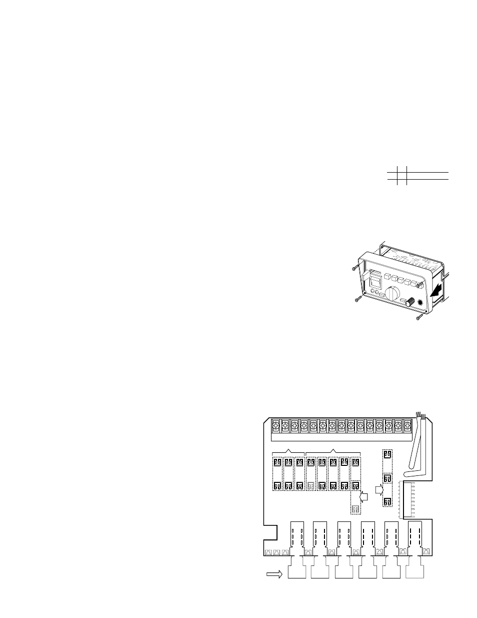
7.0 Accessing the Circuit
Board:
To access the circuit board for fuse
replacement remove the 4 front screws
and slide the chassis out (Fig. 5).
7.1 Specifications
INPUT VOLTAGE . . . . . . . . . . . . . . . . . . . . . . . . . . . . . . .12.8 VDC ±20%
INPUT CURRENT . . . . . . . . . . . . @15 VDC @ 5.5 OHMS16 AMPS MAX.
INPUT FUSE . . . . . . . . . . . . . . . . . . . . . . . . . . . . . . . . . . . . . . . . 20 AMPS
SPEAKER IMPEDANCE. . . . . . . . . . . . . . . . . . . . . . . . . . 5.5 OHMS MIN.
OPERATING TEMPERATURE . . . . . . . . . . . . . . . . . . -30° C. TO +60° C.
STORAGE TEMPERATURE . . . . . . . . . . . . . . . . . . . . -40° C. TO +70° C.
HUMIDITY . . . . . . . . . . . . . . . . . . . . . . . . . . . .99% (NON CONDENSING)
OUTPUT VOLTAGE . . . . . . . . . @ 15 VDC @ 11 OHMS 34 V RMS MAX.
OUTPUT POWER . . . . . . . . . @ 15 VDC @ 11 OHMS 105 WATTS MAX.
Fig.
6
1
Insert Fuses as Indicated
(9 Places)
Momentary
Switches
F1
F2
F5
F3
F4
F6
F7
20 amp
F8A
15 amp
15 amp
TO
P
SIDE
F8
F9A
F9
SW-1 SW-2
SW-3
SW-4
SW-5
SW-6
10"
RED
12"
RED
2 3 4 5 6 7 8 9 10 11 12 13 14 15
DEF
AUL
T