Panel descriptions, Front panel, Rear panel – Roland VC-1-DMX Video Lighting Converter User Manual
Page 2
2
Ã
Attaching the plug holder
Use the plug holder to stabilize the adaptor and
prevent the plug from accidentally coming loose.
To attach the plug holder, first remove the screw just
above the DC IN jack, align the plug holder as shown
in the illustration below and then use the screw you
just removed to affix the plug holder onto the unit.
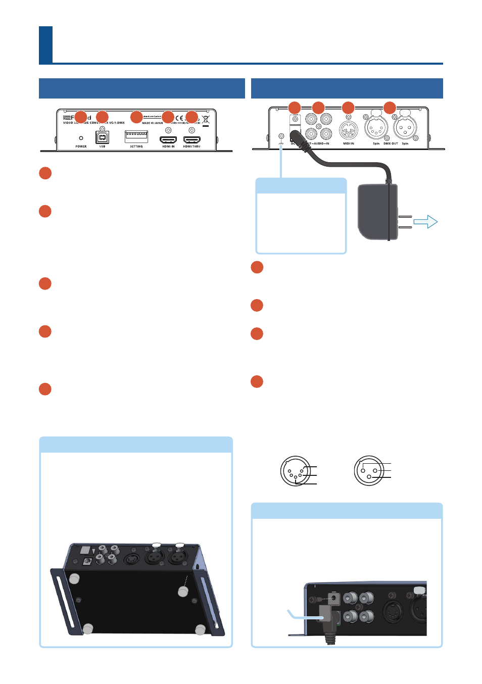
Panel Descriptions
Front Panel
1
POWER indicator
Once you connect the AC adaptor, this unit powers
up and the POWER indicator lights up red.
2
USB port
You can configure the DMX channels by connecting this
to a computer on which dedicated software is installed.
The dedicated software for use with this unit can be
downloaded from the Roland website.
https://roland.cm/VC-1-DMX/
3
SETTING switches
Use a thin pen tip or other such tool to configure
the operation settings. For the values, refer to
“Configuring the Operation Settings” (p. 4).
4
HDMI IN connector
Connect an HDMI source device such as a computer
or BD player for video input. Video signals up to a
resolution of full HD (1080/60p) can be input. HDCP-
protected video can also be input.
5
HDMI THRU connector
Outputs the video signal input from the HDMI IN
connector as-is. Connect a device that receives HDMI
video here, such as a TV monitor.
Ã
Attaching the rubber feet
This unit can be placed on a table or other surface,
and you can use screws or bands to affix it to a wall
or other flat place for use.
When placing the unit on a table, attach the included
rubber feet in the places shown in the illustration
before use.
* When turning the unit over, handle the unit
carefully; do not drop it.
Rear Panel
1
DC IN jack
Connect the included AC adaptor here. Use only
the AC adaptor that came with this unit.
2
AUDIO IN/OUT jacks
Connect an audio device.
3
MIDI IN connector
You can connect a device here that outputs MIDI,
to control DMX lighting from that external MIDI
device.
4
DMX OUT 5-pin connector/3-pin connector
These are output connectors for DMX signals.
Use either the 5-pin or the 3-pin connector,
depending on what DMX lighting equipment
you are using.
* Pin assignment of DMX OUT connectors
1
2
3
4
5
To AC outlet
1
2
3
4
Ã
Ground terminal
Connect this to an
external earth or
ground. This should
be connected when
necessary.
1: GND
2: HOT
3: COLD
※ 入力端子の場合
2: Data–
1: GND
3: Data+
※ 出力端子の場合
1: TIP:
2: RING:
3: SLEEVE:
3 2 1
HOT
COLD
GND
1: GND
2: HOT
3: COLD
※ 入力端子の場合
1: GND
2: Data–
3: Data+
※ 出力端子の場合
1: TIP:
2: RING:
3: SLEEVE:
3 2 1
HOT
COLD
GND
Plug holder