Fairchild SEMICONDUCTOR RC5051 User Manual
Page 14
AN50
APPLICATION NOTE
14
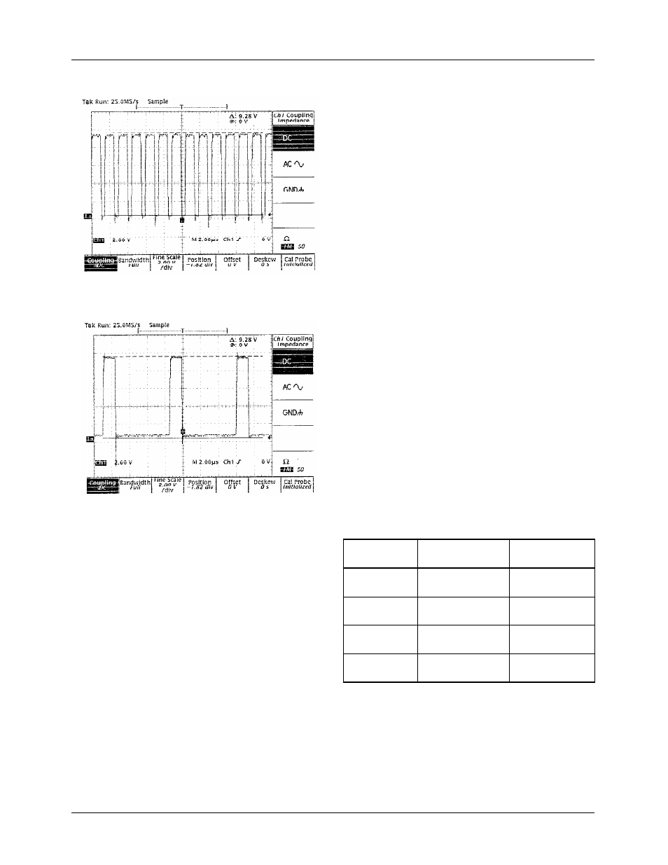
Figure 13A. V
CCQP
Output Waveform for Normal
Operation Condition with V
out
= 3.3V@10A
Figure 13B. V
CCQP
Output Waveform for
Output Shorted to Ground
Power dissipation on the Schottky diode during a short cir-
cuit condition must also be considered. During normal oper-
ation, the Schottky diode dissipates power while the power
MOSFET is off. The power dissipated in the diode during
normal operation, is given by:
During a short circuit, the duty cycle dramatically reduces to
around 20%. The forward current in the short circuit condi-
tion decays exponentially through the inductor. The power
dissipated in the diode during short circuit condition, is
approximately given by:
Thus, for the Schottky diode, the thermal dissipation during
a short circuit is greatly magnified. This requires that the
thermal dissipation of the diode be properly managed by an
appropriate heat sink. To protect the Schottky from being
destroyed in the event of a short circuit, you should limit the
junction temperature to less than 130
°
C. You can find the
required thermal resistance using the equation for maximum
junction temperature:
Assuming that the ambient temperature is 50
°
C,
Thus, you need to provide a heat sink that gives the Schottky
diode a thermal resistance of 16
°
C/W or lower to protect the
device during an indefinite short.
In summary, with proper heat sink, the Schottky diode is not
over-stressed during a short circuit condition.
Schottky Diode Selection
The application circuit diagram of Figure 3 shows a Schottky
diode, DS1. In non-synchronous mode, DS1 is used as a fly-
back diode to provide a constant current path for the inductor
when M1 is turned off. Table 10 shows the characteristics of
several Schottky diodes. Note that MBR2015CTL has a very
low forward voltage drop. This diode is ideal for applications
where the output voltage is required to be less than 2.8V.
Table 10. Schottky Diode Selection Table
Output Filter Capacitors
Output ripple performance and transient response are func-
tions of the filter capacitors. Since the 5V supply of a PC
motherboard may be located several inches away from the
DC-DC converter, the input capacitance may play an impor-
tant role in the load transient response of the RC5050 and
RC5051. The higher input capacitance, the more charge stor-
age is available for improving current transfer through the
P
D Diode
,
I
F
V
F
×
1
DutyCycle
–
(
)
×
=
=
14.5
0.5V
×
1
0.62
–
(
)
2.75W
=
×
I
F ending
,
I
sc
e
1
L R
⁄
-----------
–
×
20A
e
1.5
µ
s
1.3
µ
s
--------------
–
×
7.9A
≈
=
=
I
F ave
,
20A
7.9A
+
(
)
2
⁄
14A
≈
≈
Manufacturer
Model #
Conditions
Forward Voltage
V
F
Philips
PBYR1035
I
F
= 20A; T
j
= 25
°
C
I
F
= 20A; T
j
= 125
°
C
< 0.84v
< 0.72v
Motorola
MBR2035CT
I
F
= 20A; T
j
= 25
°
C
I
F
= 20A; T
j
= 125
°
C
< 0.84v
< 0.72v
Motorola
MBR1545CT
I
F
= 15A; T
j
= 25
°
C
I
F
= 15A; T
j
= 125
°
C
< 0.84v
< 0.72v
Motorola
MBR2015CTL
I
F
= 20A; T
j
= 25
°
C
I
F
= 20A; T
j
= 150
°
C
< 0.58v
< 0.48v
P
D Diode
,
I
F ave
,
V
F
×
1
DutyCycle
–
(
)
Ч
=
=
14
0.45
Ч
0.8
Ч
5W
≈
P
D
T
J max
(
)
T
A
–
R
Θ
JA
-------------------------------
=
R
Θ
JA
T
J max
(
)
T
A
–
P
D
-------------------------------
130
50
–
5
---------------------
16
°
C W
⁄
=
=
=