Installation diagram, Preset signal chart, Projection distance – Sony BRIGHTERA VPL-FH30 User Manual
Page 6: Computer signal, Digital tv signal, Analog tv signal
6
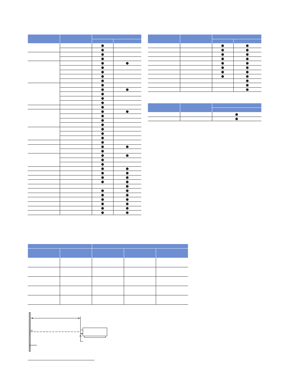
Projection Distance
Unit: inches (m)
Projection image size
Projection distance L
Diagonal
Width x Height
Standard lens
VPLL-Z1024
VPLL-Z1032
80-inch
(2.03 m)
1.72 x 1.08
(68 x 42)
2.39 – 3.83
(95 – 150)
4.00 – 5.48
(158 – 215)
5.45 – 8.32
(215 – 327)
100-inch
(2.54 m)
2.15 x 1.35
(85 x 53)
3.00 – 4.80
(119 – 189)
5.03 – 6.87
(198 – 270)
6.84 – 10.43
(270 – 410)
120-inch
(3.05 m)
2.58 x 1.62
(102 x 64)
3.61 – 5.77
(143 – 227)
6.05 – 8.27
(238 – 325)
8.24 – 12.55
(325 – 494)
150-inch
(3.81 m)
3.23 x 2.02
(127 x 79)
4.53 – 7.22
(179 – 284)
7.59 – 10.36
(299 – 408)
10.33 – 15.72
(407 – 619)
200-inch
(5.08 m)
4.31 Ч 2.69
(170 Ч 106)
6.05 – 9.64
(238 – 379)
10.15 – 13.85
(400 – 545)
13.82 – 21.00
(544 – 827)
INSTALLATION DIAGRAM
Front of the lens
Projection distance L
Projected image
Computer Signal
Resolution
fH [kHz]/
fV [Hz]
Input connector
RGB
*1
DVI-D
*2
/HDMI
*3
640 x 350
31.5/70
—
37.9/85
—
640 x 400
31.5/70
—
37.9/85
—
640 x 480
31.5/60
35.0/67
—
37.9/73
—
37.5/75
—
43.3/85
—
800 x 600
35.2/56
—
37.9/60
48.1/72
—
46.9/75
—
53.7/85
—
832 x 624
49.7/75
—
1024 x 768
48.4/60
56.5/70
—
60.0/75
—
68.7/85
—
1152 × 864
64.0/70
—
67.5/75
—
77.5/85
—
1152 x 900
61.8/66
—
1280 x 960
60.0/60
75.0/75
—
1280 x 1024
64.0/60
80.0/75
—
91.1/85
—
1400 x 1050
65.3/60
1600 x 1200
75.0/60
1280 x 768
47.8/60
1280 x 720
45.0/60
*
6
1920 x 1080
67.5/60
—
*
6
1360 x 768
47.7/60
1440 x 900
55.9/60
1680 x 1050
65.3/60
1280 x 800
49.7/60
1920 x 1200
74.0/60
*
5
*
5
1600 x 900
60.0/60
*
5
*
5
PRESET SIGNAL CHART
Digital TV Signal
Signal
fV [Hz]
Input connector
RGB/YP
B
P
R
*4
DVI-D
*2
/HDMI
*3
480i
60
576i
50
480p
60
576p
50
1080i
60
1080i
50
720p
60
*
6
720p
50
1080p
60
—
*
6
1080p
50
—
1080p
24
—
Analog TV Signal
Signal
fV [Hz]
Input connector
VIDEO/S VIDEO
NTSC
60
PAL/SECAM
50
*1: INPUT A, INPUT B
*2: INPUT C
*3: INPUT D
*4: INPUT A
*5: Available for VESA Reduced Blanking signals only.
*6: INPUT C is determined as a computer signal;
INPUT D is determined as a digital TV signal.
• When a signal other than the signals listed in the table is input, the picture
may not be displayed properly.
• An input signal meant for a screen resolution different to that of the panel
will not be displayed in its original resolution. Text and lines may be uneven.
• Some actual values may differ slightly from the design values given in the
table.