Zxld1615 – Diodes ZXLD1615 User Manual
Page 9
Diode selection
The rectifier diode (D1) should be a fast low
capacitance schottky diode with low reverse leakage
at the working voltage. It should also have a peak
current rating above the peak coil current and a
continuous current rating higher than the maximum
output load current.
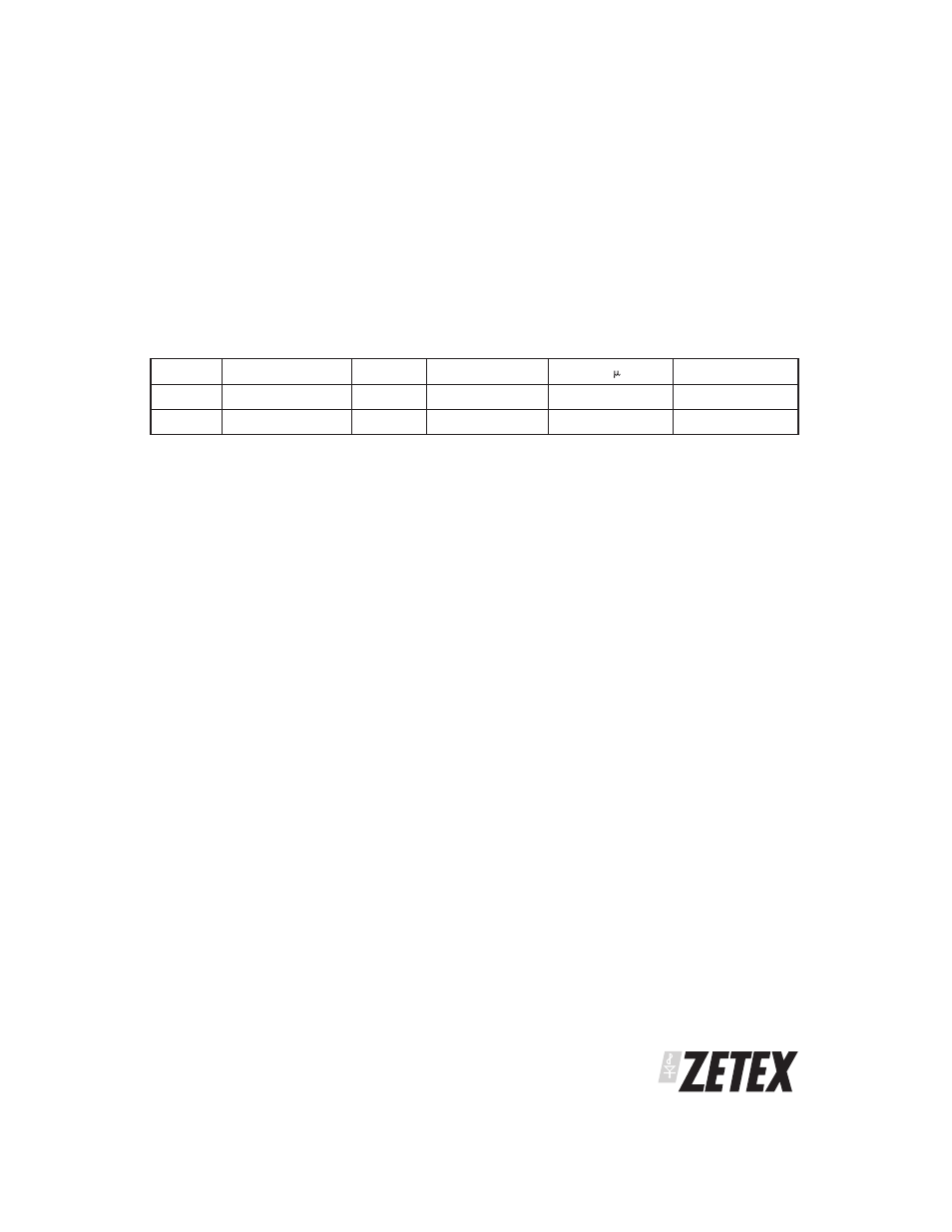
The table below gives some typical characteristics for
diodes that can be used with the ZXLD1615:
Diode
V
F
@ 100mA (mV)
I
FSM
(mA)
Ic (mA)
I
R
at 30V ( A)
Package
ZHCS400
300
1000
400
15
SOD323
ZHCS500
300
1000
500
15
SOT23
Layout considerations
PCB tracks should be kept as short as possible to
minimize ground bounce, and the ground pin of the
device should be soldered directly to the ground
plane. It is particularly important to mount the coil
and the input/output capacitors close to the device to
minimize parasitic resistance and inductance, which
will degrade efficiency. The FB pin is a high
impedance input, so PCB track lengths to this should
also be kept as short as possible to reduce noise
pickup. Excess capacitance from the FB pin to ground
should be avoided.
ZXLD1615
S E M I C O N D U C T O R S
ISSUE 3 - AUGUST 2004
9