Installation (continued), Maintenance – Blue Angel Pumps BCP20ULS User Manual
Page 4
Operating Instructions and Parts Manual
4
www.blueangelpumps.com
Installation
(Continued)
STEP 5: INSTALLATION OF
SAFETY SWITCH (IF APPLICABLE)
Connect power cord
to a constant
voltage source. Do not connect to a fan
or other device that may run
intermittently.
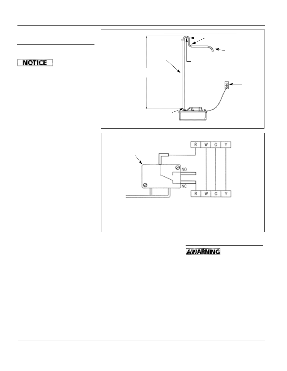
A. The pump can be wired directly to
the appliance thermostat to shut
the pump and appliance down in
the event of pump failure. Refer to
Figure 7 for typical wiring diagram.
NOTE: The alarm can be wired in the
safety switch at the normally open
(“NO”) contact.
TIPS FOR EASY INSTALLATION
1. After reading instructions, check to
make sure installation does not
exceed a maximum of 15 feet of
vertical lift.
2. Make sure pump is level. No part of
the pump base should be more
than 1/8” off of level plane.
3. Use soapy water on unit when
performing cleaning maintenance.
(Refer to Maintenance guidelines.)
4. For optimum performance, drain
and discharge lines should have a
continuous downward slope. Test
operation of pump to make sure
lines have enough downward slope
for efficient operation.
5. Avoid overtightening of check valve
after cleaning. (Refer to
Maintenance gudelines.)
6. Use constant voltage power source.
Do not plug into a device that runs
intermittently.
7. Locate model number and date
code on pump and take note of
them.
8. To assure proper performance, the
highest point of discharge line
should be higher than 5’ off the
floor.
9. Clean any debris in the pump
reservoir if necessary.
10. Do not handle the pump until you
have disconnected it from the
power source. Follow all guidelines
Figure 6 - Installation of discharge line
Figure 7 - Typical wiring diagram for pumps provided with safety switch
NOTE: The alarm can be wired into the safety
switch at the normally open (“NO”) contact.
for electrical safety discussed in
General Safety.
11. Do not use a pump discharge pipe
smaller than the pump discharge
size.
12. After installation, test pump to
make sure that system is working
properly.
13. Make sure that installation
conforms to all local and national
codes.
14. Local codes may require the use of a
condensate neutralizer when using
this pump.
Maintenance
Make certain that
the pump is
unplugged before attempting to
service or remove any component. This
pump is assembled in the factory using
special equipment; therefore only
authorized service dealers or qualified
electricians should attempt to repair
this unit. Improper repair can cause an
electrical shock hazard.
CLEANING RESERVOIR AND
IMPELLER
1. Unscrew two screws through
mounting brackets, and remove
pump from wall, if mounted.
15 Ft.
Max
Inverted “U”
To Main Drain
Hose clamp
(recommended, not included)
GFCI
Outlet
Do not kink or pinch
3/8” ID Tubing
Typical Thermostat
Typical Thermostat Connections of Appliance
Overflow
Safety Switch