Parts replacement caution – Nexen 5H30P-E 913005 User Manual
Page 10
7
FORM NO. L-20203-F-1209
PARTS REPLACEMENT
CAUTION
Working with spring loaded or tension
loaded fasteners and devices can cause
injury. Wear safety glasses and take the
appropriate safety precautions.
18
14
19
Hub and
Piston/Cylinder
Assembly
4
Drive Flange
Assembly
14
Cylinder/Piston
Assembly
1
8
FIGURE 4
FIGURE 3
FIGURE 5
13
12
Drive Flange
Assembly
FIGURE 6
22
Cylinder/Piston
Assembly
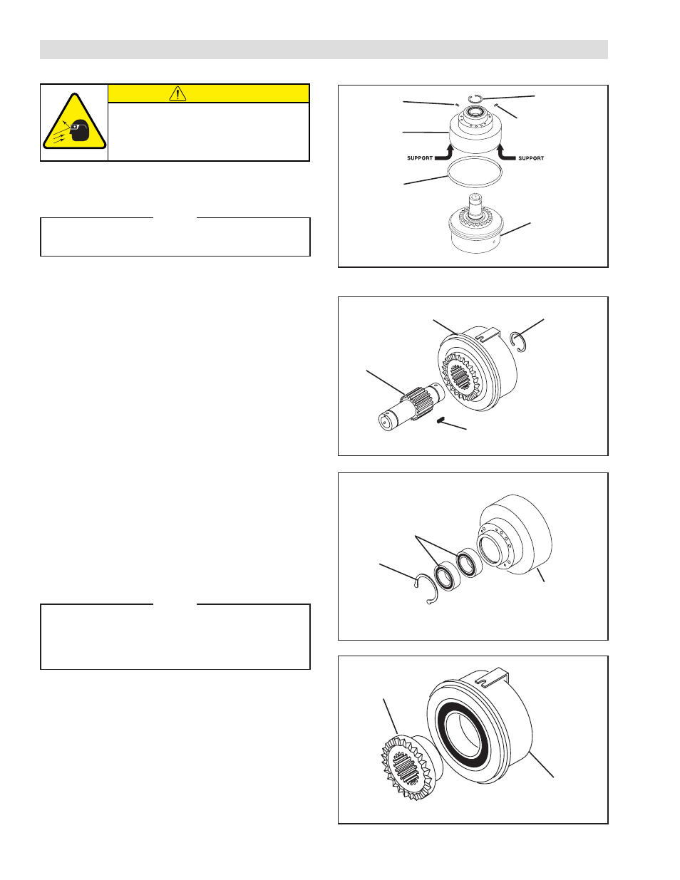
* Item 19 is a locking collar in 5H80P-E models.
REFER TO FIGURES 3‑6.
1. Remove the Set Screws (Item 18 and 19).
NOTE
A Locking collar with three set screws is used
in 5H80P-E models.
2. Remove the Retaining Ring (Item 14).
3. Fully supporting the lip of Drive Flange Assembly
press the Hub (Item 1) and Piston/Cylinder
Assembly out of the Drive Flange Assembly.
4. Remove the old Rotary Seal (Item 4).
5. Remove the Retaining Ring (Item 14).
6. Fully supporting the Cylinder/Piston Assembly,
press the Hub (Item 1) out of the Cylinder/Piston
Assembly.
7. Remove the old Compression Springs (Item 8).
8. Remove the Retaining Ring (Item 13).
9. Press the old Ball Bearings (Item 12) out of the Drive
Flange Assembly.
10. Clean bore of Drive Flange Assembly with fresh
solvent making sure all old Loctite
®
residue is
removed.
NOTE
When installing new Ball Bearings, carefully
align the Ball Bearing O.D. with Drive Flange
Assembly bore to prevent Ball Bearing
misalignment.
11. Apply an adequate amount of Loctite
®
680 to evenly
coat the outer race of the new Ball Bearings (Item
12); then, press the new Ball Bearings into the Drive
Flange Assembly.
12. Reinstall the Retaining Ring (Item 13).
13. Remove the Drive Flange (Item 22) from the Piston
Cylinder Assembly.
- 5H35P-E 913015 5H40P-E 913025 5H45P-E 913035 5H60P-E 913097 5H60P-E 913114 5H50P-E 913045 5H50P-E 913057 5H60P-E 913055 5H60P-E 913065 5H30P-E 913006 5H30P-E 913000 5H30P-E 913115 5H35P-E 913082 5H35P-E 913010 5H40P-E 913020 5H45P-E 913084 5H50P-E 913078 5H45P-E 913089 5H60PSP-E 913081 5H45P-E 913030 5H45P-E 913128 5H50P-E 913091 5H50P-E 913040 5H60P-E 913075 5H50P-E 913069 5H60P-E 913050 5H80P-E 913170 5H80PSE-E 913171 5H30P-E 913008 5H35P-E 913018 5H40P-E 913028 5H45P-E 913038 5H50P-E 913048 5H60P-E 913058