Nexen 5H30P-E 913005 User Manual
Page 6
3
FORM NO. L-20203-F-1209
NOTE
Nexen 5HP-E is shaft mounted using a
customer supplied full length key.
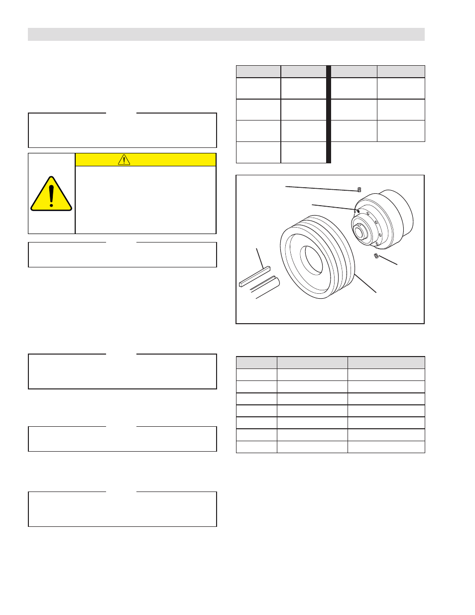
REFER TO FIGURE 1.
1. Install Nexen Clutch Coupling, Bearing Supported
Pulley, Sprocket, or Gear (See Table 2).
2. Insert customer supplied key into shaft.
3. Slide Clutch onto shaft and customer supplied key.
NOTE
Whenever possible, arrange the input drive to
the clutch through the drive flange to prevent
clutch bearings from rotating unnecessarily.
4. Using Set Screws (Item 18 and 19*), secure Clutch
to shaft.
NOTE
A locking collar with three set screws is used
in 5H80P-E models.
5. Tighten Set Screws (Item 18 and 19*) to
recommended torque (See Table 3).
NOTE
Align air inlet port to the six o'clock down
position to allow condensation to drain out
of the exhaust port.
FIGURE 1
Nexen 5HPE Series clutches have a drive flange with two
bearings, a pilot diameter, and tapped holes for mounting
a pulley, sprocket, or the Nexen Clutch Coupling (Refer to
Sales Brochure L-21479) (See Table 2 for recommended
tightening torques).
NOTE
Nexen recommends using a red anaerobic
thread locking compound on Pilot Mounting
Bolts.
INSTALLATION
TABLE 2 RECOMMENDED TIGHTENING TORQUES
TABLE 3 RECOMMENDED TIGHTENING TORQUES
Do not connect in-line without the use
of a flexible coupling half. The internal
construction of 5HPE and Series Clutches
will not allow any misalignment tolerances.
If a coupling is required, use the Nexen
Clutch Coupling (Refer to Nexen Clutch
Coupling brochure 20208).
CAUTION
Model
Torque
Model
Torque
5H30P-E
13 ft-lbs
[17.6 Nm]
5H50P-E
48 ft-lbs
[65 Nm]
5H35P-E
13 ft-lbs
[17.6 Nm]
5H60P-E
48 ft-lbs
[65 Nm]
5H40P-E
13 ft-lbs
[17.6 Nm]
5H80P-E
119 ft-lbs
[161.3 Nm]
5H45P-E
13 ft-lbs
[17.6 Nm]
Model
Torque (Item 18)
Torque (Item 19)
5H30P-E
21 in-lbs [2.4 Nm]
61 in-lbs [6.9 Nm]
5H35P-E
21 in-lbs [2.4 Nm]
61 in-lbs [6.9 Nm]
5H40P-E
21 in-lbs [2.4 Nm
61 in-lbs [6.9 Nm]
5H45P-E
21 in-lbs [2.4 Nm
61 in-lbs [6.9 Nm]
5H50P-E
21 in-lbs [2.4 Nm
61 in-lbs [6.9 Nm]
5H60P-E
21 in-lbs [2.4 Nm
61 in-lbs [6.9 Nm]
5H80P-E
21 in-lbs [2.4 Nm
61 in-lbs [6.9 Nm]
In severe use applications, the clutch may tend to move axially along the shaft. To prevent axial movement, confine the
clutch between shoulders, clamp collars, or insert spring pins through the shaft.
Mounting positions of Tooth Clutches may be horizontal or vertical. Nexen recommends the Drive Flange faces up to en-
hance the spring return when mounting tooth clutches in the vertical position.
Set Screw
(Item 18)
Clutch
Customer
Supplied Key
Set Screw
(Item 19)*
Bearing Supported
Pulley, Sprocket,
or Coupling
* Item 19 is a locking collar in 5H80P-E models.
- 5H35P-E 913015 5H40P-E 913025 5H45P-E 913035 5H60P-E 913097 5H60P-E 913114 5H50P-E 913045 5H50P-E 913057 5H60P-E 913055 5H60P-E 913065 5H30P-E 913006 5H30P-E 913000 5H30P-E 913115 5H35P-E 913082 5H35P-E 913010 5H40P-E 913020 5H45P-E 913084 5H50P-E 913078 5H45P-E 913089 5H60PSP-E 913081 5H45P-E 913030 5H45P-E 913128 5H50P-E 913091 5H50P-E 913040 5H60P-E 913075 5H50P-E 913069 5H60P-E 913050 5H80P-E 913170 5H80PSE-E 913171 5H30P-E 913008 5H35P-E 913018 5H40P-E 913028 5H45P-E 913038 5H50P-E 913048 5H60P-E 913058