Nexen 5H30P-E 913005 User Manual
Page 11
8
FORM NO. L-20203-F-1209
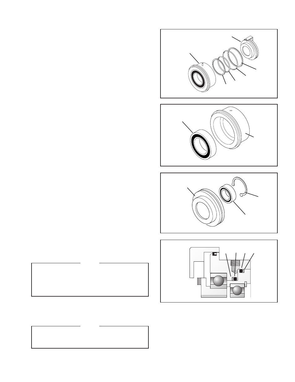
REFER TO FIGURES 7‑10.
14. Separate Piston (Item 3) from Cylinder (Item 2).
15 Remove the old O-ring Seals (Items 15 and 16) and
Back Up Seals (Items 20 and 21) from the Piston
(Item 3) and Cylinder (Item 2).
16. Press Ball Bearing (Item 11) out of Cylinder (Item 2).
17. Clean the bearing bore of the Cylinder (Item 2) with
fresh solvent making sure all old Loctite
®
residue is
removed.
18. Apply an adequate amount of Loctite
®
680 to
evenly coat the outer race of the new Ball Bearing
(Item 11); then, press the new Ball Bearing into the
Cylinder (Item 2).
18. Remove the Retaining Ring (Item 13) from the Piston
(Item 3).
19. Press the old Ball Bearing (Item 12) out of the Piston
(Item 3).
20. Clean bearing bore of Piston (Item 3) with fresh
solvent. Make sure all old Loctite
®
residue is removed.
21. Apply an adequate amount of Loctite
®
680 to evenly
coat the outer race of the new Ball Bearing (Item
12); then, press the new Ball Bearing into the Piston
(Item 3).
22. Reinstall the Retaining Ring (Item 13).
23. Coat o-ring contact surfaces of Piston (Item 3) and
Cylinder (Item 2) with a thin film of o-ring lubricant.
24. Coat the new O-ring Seals (Items 15 and 16) with a
thin film of o-ring lubricant.
NOTE
When installing new O-ring Seals and Back-
up Rings make sure the curved surface of the
Back-up Ring matches surface of O-ring Seal.
The Back-up Rings must be installed on the
non-pressurized side of the O-ring Seals.
25. Install the new O-ring Seals (Items 15 and 16) and
Back-up Rings (Items 20 and 21) on the Piston (Item
3) and Cylinder (Item 2).
NOTE
Use caution when pressing the Piston into
the Cylinder to avoid damaging O-ring Seals
and Back-up Rings.
26. Press the Piston (Item 3) into the Cylinder (Item 2).
PARTS REPLACEMENT (continued)
FIGURE 7
FIGURE 8
FIGURE 9
FIGURE 10
2
21
16
15
20
3
11
2
13
12
3
21 16 15 20
- 5H35P-E 913015 5H40P-E 913025 5H45P-E 913035 5H60P-E 913097 5H60P-E 913114 5H50P-E 913045 5H50P-E 913057 5H60P-E 913055 5H60P-E 913065 5H30P-E 913006 5H30P-E 913000 5H30P-E 913115 5H35P-E 913082 5H35P-E 913010 5H40P-E 913020 5H45P-E 913084 5H50P-E 913078 5H45P-E 913089 5H60PSP-E 913081 5H45P-E 913030 5H45P-E 913128 5H50P-E 913091 5H50P-E 913040 5H60P-E 913075 5H50P-E 913069 5H60P-E 913050 5H80P-E 913170 5H80PSE-E 913171 5H30P-E 913008 5H35P-E 913018 5H40P-E 913028 5H45P-E 913038 5H50P-E 913048 5H60P-E 913058