Caution – Nexen 5H20S/4 911394 User Manual
Page 10
7
FORM NO. L-20211-B-0110
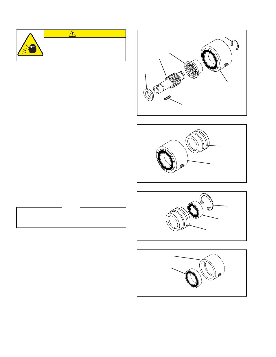
REFER TO FIGURES 5-8.
1. Remove Retaining Ring (Item 11).
2. Slide Hub (Item 1) out of Piston/Cylinder Assembly.
3. Slide Backing Plate (Item 7) off Hub (Item 1).
4. Remove Compression Springs (Item 20) from Drive
Ring (Item 2).
5. Slide Drive Ring (Item 2) out of Cylinder/Piston
Assembly.
6. Separate Piston (Item 4) from Cylinder (Item 5).
7. Remove Retaining Ring (Item 10) from Piston (Item
4).
8. Press Bearing (Item 8) out of Piston (Item 4).
9. Clean bore of Piston with fresh safety solvent.
10. Apply Loctite
®
601 to O.D. of new Bearing, then
press new Bearing into Piston.
NOTE
When installing new Bearings, carefully align
Bearing O.D. with Piston bore to prevent Bearing
misalignment.
11. Press Bearing (Item 9) out of Cylinder (Item 5).
12. Clean bore of Cylinder with fresh safety solvent.
13. Apply Loctite
®
601 to O.D. of new Bearing, then
press new Bearing into Cylinder.
BEARING REPLACEMENT (CYLINDER/PISTON ASSEMBLY)
FIGURE 5
11
Cylinder/Piston
2
1
7
20
FIGURE 6
FIGURE 7
FIGURE 8
4
5
10
8
4
5
9
CAUTION
Working with spring loaded or tension
loaded fasteners and devices can cause
injury. Wear safety glasses and take the
appropriate safety precautions.