Caution – Nexen 5H20S/4 911394 User Manual
Page 11
8
FORM NO. L-20211-B-0110
O-RING & BACK-UP RING REPLACEMENT
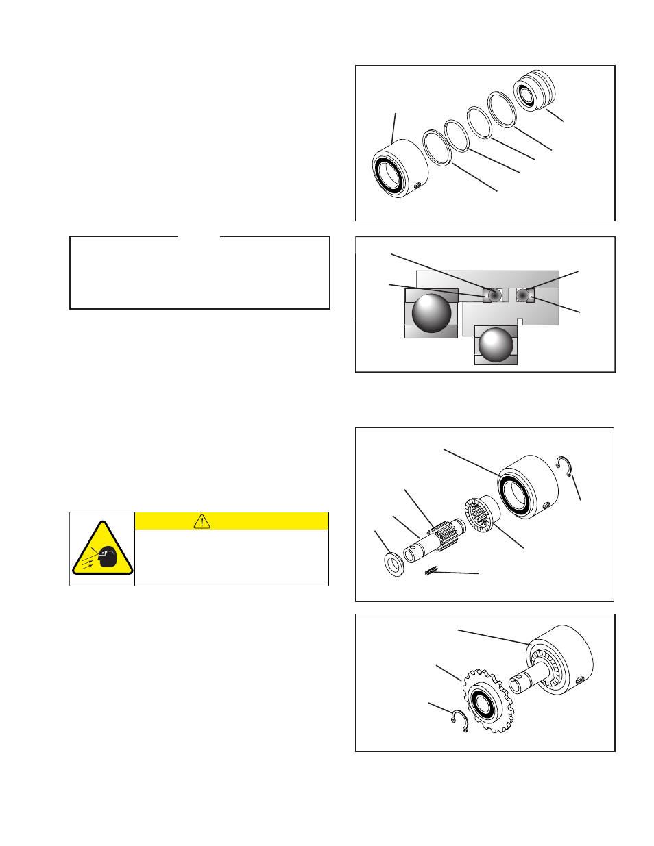
REFER TO FIGURES 9 & 10.
1. Separate Cylinder (Item 5) and Piston (Item 4).
2. Remove O-rings (Items 13 & 14) and Back-up Rings
(Items 12 & 15) from Cylinder and Piston.
3. Clean o-ring grooves of Cylinder and Piston; then
lubricate new o-rings and o-ring grooves of Piston
and Cylinder with fresh o-ring lubricant.
4. Install new O-rings (Items 13 & 14) and Back-up
Rings (Items 12 & 15).
NOTE
When installing new O-rings and Back-up
Rings, make sure curved surface of Back-up
Ring matches surface of O-ring. Back-up Rings
must be installed on the non-pressurized side
of the O-rings.
5. Carefully slide Piston (Item 4) into Cylinder (Item 5),
to avoid damaging seals.
FIGURE 10
13
12
14
15
FIGURE 9
Cylinder
Piston
15
13
14
12
5H20S/4 REASSEMBLY
REFER TO FIGURES 11 & 12.
1. Slide Drive Ring (Item 2) into Cylinder/Piston
Assembly.
2. Lubricate splines of Hub (Item 1) with NEVER-
SEEZ
®
.
FIGURE 11
FIGURE 12
11
Cylinder/Piston
Lubricate with
Never-Seez®
1
2
7
20
Cylinder/Piston
Assembly
Drive Sprocket
Assembly
Retaining Ring
(Item 11)
3. Slide Hub (Item 1) into Drive Ring (Item 2), and
replace Retaining Ring (Item 11).
4. Install Compression Springs (Item 20) into
respective holes of Drive Ring (Item 2).
5. Slide Backing Plate (Item 7) onto Hub (Item 1).
6. Slide Drive Sprocket Assembly onto Hub (Item 1)
and Cylinder/Piston Assembly.
7. Replace Retaining Ring (Item 11).
CAUTION
Working with spring loaded or tension
loaded fasteners and devices can cause
injury. Wear safety glasses and take the
appropriate safety precautions.