Nexen 5H45PSE 910225 User Manual
Page 14
14
FORM NO. L-20255-E-0213
5HP-SE-E, PILOT MOUNT, ENCLOSED (continued)
REFER TO FIGURES 10-18.
21. Coat o-ring contact surfaces of the Piston (Item 3) and
Cylinder (Item 2) with a thin film of o-ring lubricant.
22. Coat the new O-ring Seals (Items 12 and 13) with a
thin film of o-ring lubricant.
23. Install the new O-ring Seals (Items 12 and 13) on the
Piston (Item 3) and Cylinder (Item 2).
NOTE
Use caution when pressing the Piston into
the Cylinder to avoid damaging O-ring Seals.
24. Press the Piston (Item 3) into the Cylinder (Item 2).
25. Install Die Springs (Item 22) into the Spring Housing
(Item 20) sockets.
26. Position the Spring Housing over the Cylinder/Piston
assembly, align the clearance holes with the tapped
holes in the Cylinder.
27. Insert Cap Screws (Item 23) into the Spring Housing and
tighten alternately and evenly until the Spring Housing
is flush with the Cylinder. Torque the Cap Screws to
the values shown in Table 5.
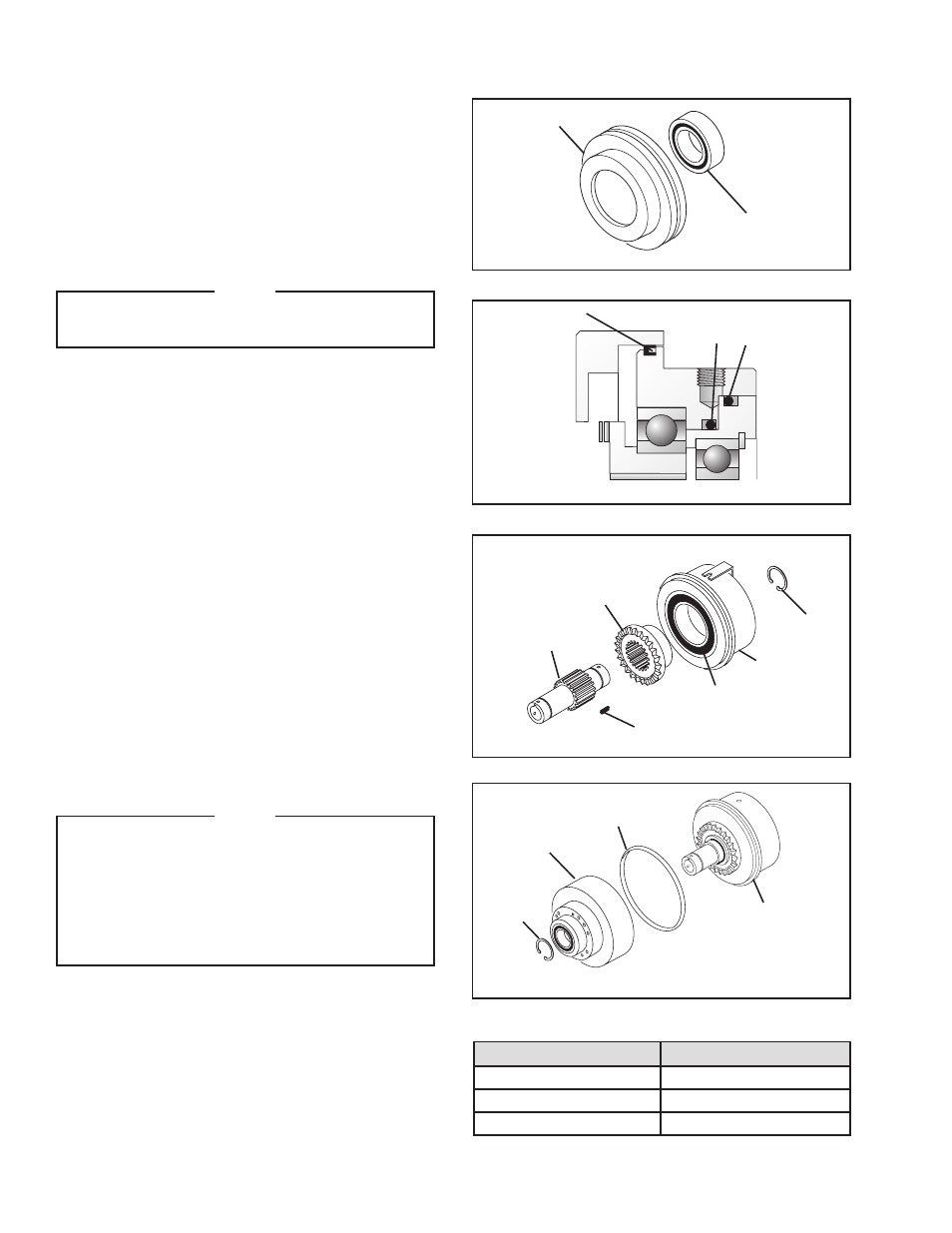
28. Slide the Drive Flange (Item 4) into the Cylinder (Item
2) and Ball Bearing (Item 8).
29. Coat the spline teeth of the Hub (Item 1) with Never-
Seez
®
and slide the Hub (Item 1) into the Drive Flange.
30. Reinstall the Retaining Ring (Item 11).
31. Install the new Rotary Seal (Item 7) into the groove in
the Cylinder.
NOTE
The back of the Rotary Seal must be installed
facing the Drive Flange Assembly end of the
clutch.
Use caution when sliding Drive Flange
Assembly onto Cylinder/Piston Assembly to
avoid damage to Rotary Seal.
FIGURE 15
8
3
FIGURE 17
4
2
8
18
1
11
Model
Tightening Torque
5H60PSE-E
20 ft-lbs
5H80PSE-E
25 ft-lbs
5H100PSE-E*
30 ft-lbs
FIGURE 18
Drive Flange
Assembly
11
7
Cylinder/Piston
Assembly
TABLE 5
*Item #20, Model 5H100PSE-E.
FIGURE 16
13 12
Rotary Seal
(Item 7)
- 5H45PSE 910224 5H45PSE-E 910204 5H45PSE 910226 5H60PSE-E 910410 5H60PSE-E 910424 5H35PSE 910093 5H30-SE 906701 5H30P-SE 906708 5H35PSE 910091 5H35-SE 910098 5H35-SE 910097 5H50PSE 910325 5H50-SE 907106 5H50PSE 910321 5H50PSE 910304 5H60PSE 910407 5H50-SE 907101 5H50PSE 910323 5H60PSE 910432 5H60PSE 910404 5H60-SE 910408 5H60PSE 910446 5H80PSE-E 913172 5H35SE 910122 5H35SE 910089 5H35PSE 910094 5H35SE 910121 5H50PSE 910326 5H60PSE 910419 5H60PSP-SE 910440