Nexen BD 933702 User Manual
Page 5
5
FORM NO. L-21098-C-0609
9. Press in the Pivot Pins (Item 7) (See Figure 2).
10. Reinsert the Pivot Pin Retaining Plate (Item 6) (See Figure
2).
11. Reinstall the four Cap Screws (Item 24) and tighten to 40-50
in-lb [4.5-5.6 Nm] torque.
NOTE: When reinstalling the Shoe (Item 3), first place the
Belleville Disc Springs (Item 29) into the recesses provided
in the Brake Arm (Item 2). The Belleville Disc Springs should
be inserted with their concave side toward the Brake Arm.
12. Reinstall the Shoes (Item 3) and Belleville Disc Springs (Item
29) (See Figure 2).
13. Reinsert the Detent Pins (Item 16) to secure the Shoes (Item
3) and Belleville Disc Springs (Item 29) (See Figure 2).
14. Loosen the Nut to manually reset the brake.
15. Remove the Threaded Rod, Nut, and Washer.
16. Screw the Vent (Item 17) into the back of the Actuator until
hand tight and continue to tighten one and one-half turns.
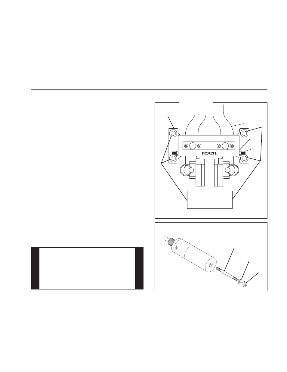
MAIN FRAME
NOTE: Set Screws (Item 50) and Hex. Nuts (Item 51) are
provided to hold Brake Arms (Item 2) in place when the BD
Caliper Brake is used on vertical shaft installations (See
Figure 3).
1. Locate the BD Caliper Brake in the desired position in relation
to the disc.
NOTE: This BD Caliper Brake is spring engaged and
hydraulically disengaged. To release the spring pressure,
remove the Vent, then lubricate and insert a Class 8.8 M10-
1.5 x 5.5'' Threaded Rod into the back of the Actuator; then,
using a Flat Washer and Nut, tighten the Nut to release
the spring pressure (See Figure 4). A Manual Release Kit
(Product No. 933710) containing these items is available
from Nexen.
2. Align the customer supplied support with the Main Frame
(Item 1) mounting holes.
NOTE: The support must be capable of sustaining loads
produced during braking.
If shims are used under the Main Frame (Item 1) mounting
pads, care must be taken to prevent warping of the Main
Frame when tightening the customer supplied 5/8''-11 cap
screws (See Figure 3).
Flat Washer
Nut
Threaded Rod
FiGuRE 3
2
50
1
Customer supplied
5/8''-11 cap screws
and lock washers
51
FiGuRE 4
3. Tighten the customer supplied 5/8''-11 cap screws to 150 ft-
lb [203.4 Nm] torque.
4. Remove the Threaded Rod, Nut, and Washer.
5. Screw the Vent (Item 17) into the back of the Actuator until
hand tight and continue to tighten one and one-half turns.
NOTE: The Vent in the Rear Cylinder prevents debris from
entering the Nested Spring stack and relieves any pressure
built up by the reciprocating action of the Piston.
WArNINg
The customer supplied 5/8''-11 cap screws
must sustain the loads produced by the
braking preload produced by mounting
torque. The torque rating specified above al-
lows a significant load safety factor. DO NOT
OVEr TOrQUE CAP SCrEWS.